Supercharge Your Innovation With Domain-Expert AI Agents!

Concrete pipe manufacturing equipment and method

A technology for concrete pipes and manufacturing equipment, used in life-saving equipment, other equipment, manufacturing tools, etc., can solve the problems of inability to accurately control the speed relationship, inability to control sufficiently accurately, and inapplicability, and achieve easy connection and separation. Increase and avoid errors

Inactive Publication Date: 2007-07-11
INT PIPE MACHINERY
View PDF3 Cites 0 Cited by
  • Summary
  • Abstract
  • Description
  • Claims
  • Application Information

AI Technical Summary

Problems solved by technology

The cage twisting phenomenon can be substantially reduced by the system disclosed in the 4,549,539 patent, but the speed ratio relationship between the roller head and trowel cannot be controlled with sufficient precision in current equipment to completely eliminate cage twisting
More importantly, due to the inability to accurately control the aforementioned speed relationship, the current system is not suitable for the most economical and consistent high-quality pipe body that can be produced because the operator’s judgment and possible misjudgment are no longer required. known automatic control system

Method used


Image

  • Concrete pipe manufacturing equipment and method
  • Concrete pipe manufacturing equipment and method
  • Concrete pipe manufacturing equipment and method

Examples


Embodiment Construction

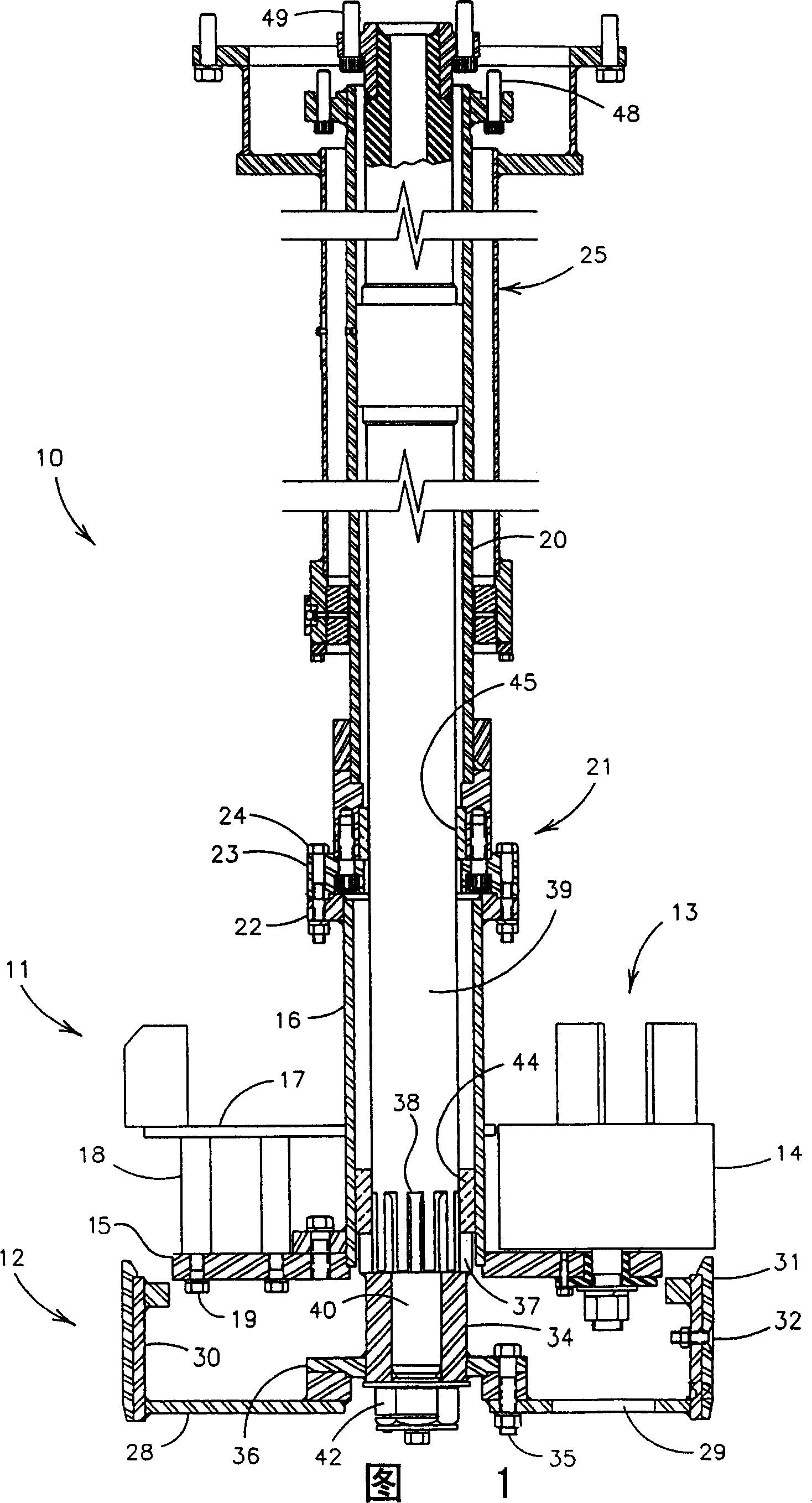
[0016] Please refer to Fig. 1, an existing reverse filling head assembly (hereinafter referred to as filling head) is represented by 10, and this filling head comprises a roller assembly represented by 11, or simply referred to as a roller head, and A trowel assembly generally referred to as a trowel and indicated at 12.

[0017] The roller head 11 includes a roller assembly indicated by 13 , and the roller assembly 13 includes a plurality of smoothing rollers, usually four, and one of the smoothing rollers is indicated by 14 . The roller 14 is supported by a roller mounting plate 15 , and the roller mounting plate 15 is connected with the lower driving tube 16 . A roller cage occupied between the rollers 14 is indicated at 17, the function of this roller cage is to intercept wet concrete from above before it falls below the top of the rollers 14 and also to ensure that the wet concrete The flow is radially outward to the inner wall of the mold, not shown. The roller cover 1...


PUM


Abstract

A concrete pipe making machine having a packerhead consisting of a rollerhead and a longbottom in which the rollerhead and longbottom are quickly assembleable and disassembleable as a unit from the packerhead drive means with one connector and brought into final adjustment off the machine, said drive means providing no obstruction to the flow of wet concrete toward the compaction area, the speed ratios between the rollerhead and longbottom being infinitely variable, and easily replaceable protective wear rings for precluding erosive deformation of the permanent parts of the machine due to undesired penetration of wet concrete into the longbottom .

Description

technical field [0001] The present invention relates to a concrete pipe manufacturing apparatus and method, and more particularly to a filling head system for manufacturing concrete pipes such as those disclosed in US Pat. Nos. 4,540,539 and 5,080,571. Background technique [0002] In filling head systems for the manufacture of concrete pipes, a filling head consisting of a roller head or roller assembly and a trowel commonly referred to as a trowel (longbottom) is lowered into a circular mold and as they go up Rotate when moving, and fill and press the wet concrete dropped on the filling head against the inner wall surface of the mold all the time. While well-functioning equipment producing good-quality wire-reinforced and unreinforced pipe bodies can be used as disclosed in the 4,540,539 patent and as illustrated by improvements thereto in the 5,080,571 patent, the power requirements of the market require Then improve the quality of the pipe body. [0003] Therefore, it ...

Claims


Application Information

Patent Timeline
Patent Type & Authority Patents(China)
IPC IPC(8): B28B21/26
CPCB28B21/26A01K29/00A62B18/02
Inventor 托马斯D·格劳拜伦M·希尔茨
Owner INT PIPE MACHINERY
Features
  • R&D
  • Intellectual Property
  • Life Sciences
  • Materials
  • Tech Scout
  • Unparalleled Data Quality
  • Higher Quality Content
  • 60% Fewer Hallucinations
Learn More