Multiple double-cavity conjoined capsule type high flow leakproof pump
What is Al technical title?
Al technical title is built by PatSnap Al team. It summarizes the technical point description of the patent document.
A large flow, pump body technology, applied in the field of large flow non-leakage pumps, can solve the problems of short life, poor corrosion resistance, corrosion, etc., and achieve the effect of improving the service life
Active Publication Date: 2007-07-18
吴长海 +1
View PDF8 Cites 0 Cited by
Summary
Abstract
Description
Claims
Application Information
AI Technical Summary
This helps you quickly interpret patents by identifying the three key elements:
Problems solved by technology
Method used
Benefits of technology
Problems solved by technology
[0003] In the use of traditional pumps, most of the conveying part and the transmission part are integrated. After a long time of use, the sealing degree drops rapidly, and the fluid begins to leak outward, causing serious corrosion of gears, blades and bearings, and great damage, especially The corrosion of acid and alkaline fluid medium is more serious, the function is extremely reduced, or even completely scrapped, which not only affects production, but also pollutes the environment
[0004] Most of today's anti-corrosion pumps are made of stainless steel, which has disadvantages such as difficult processing, high power consumption, high cost, poor anti-corrosion, easy leakage, and short service life.
Method used
Image
Click on the blue label to locate the original text in one second.
Reading with bidirectional positioning of images and text.
Examples
Embodiment Construction
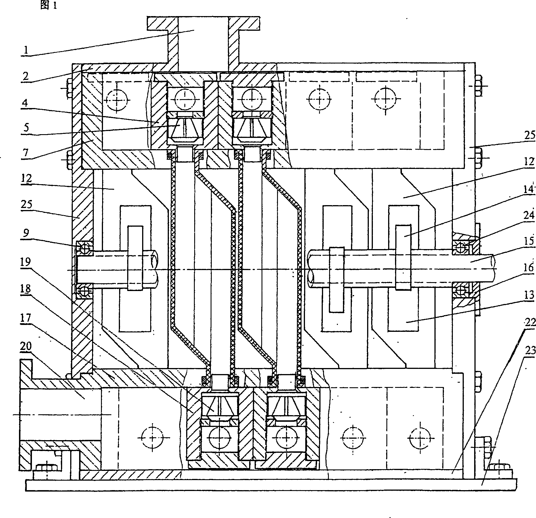
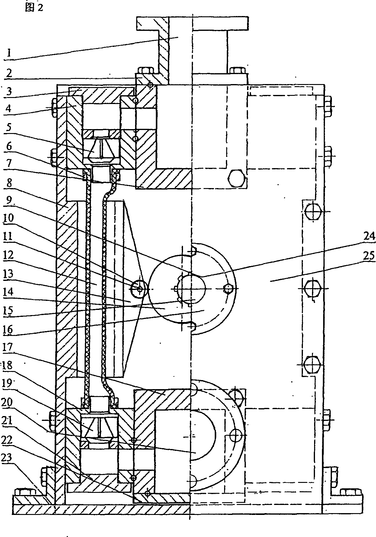
[0013] Referring to Fig. 1, the pump body is made up of a high-pressure water storage tank 7, a low-pressure water storage tank 17, two main boards 8, and two side plates 25. The main shaft 15 is arranged on the side plates 25 through bearings 9 and 24, and five The cam 14 is installed on the main shaft 15, the main shaft 15 is connected with a -3.2KW motor (not shown) and rotates around the center of the bearings 9 and 24 under the drive of the motor, thereby driving each cam 14 to rotate, so that each cam 14 drives the corresponding The pressure support 13 of the pressure support 13 makes a linear reciprocating motion, so that each pressure support 13 repeatedly squeezes ten double-chamber conjoined capsules 12 connected in parallel in two rows on the opposite side, and the two ports of each double-chamber conjoined capsule 12 are respectively connected to the high-pressure valve chamber 4 and the low-pressure The valve chamber 18 makes the high-pressure valve 5 and the low-p...
PUM
Abstract
The present invention proposes one kind of pump including pump body, driving part and fluid medium conveying part. The pump features that the pump body consists of high pressure water tank, low pressure water tank, two main plates and two side plates; the double cavity bags in double rows constituting the fluid medium conveying part are installed on two sides of the high pressure water tank and the low pressure water tank and communicated with the high pressure water tank and the low pressure water tank via the high pressure valve and the low pressure valve separately inside the high pressure valve chamber and the low pressure valve chamber; and the bearings, main shaft, the cam and the pressure rack constituting the driving part are installed on two side plates.
Description
technical field [0001] The invention relates to a large-flow non-leakage pump which utilizes volume changes of multiple double-cavity conjoined sacs to suck or press out fluid. Background technique [0002] Most of the various types of pumps used at home and abroad today use gears, vanes, etc., and each pump has 4 constants, A, constant speed, B, constant flow, C, constant head, D, constant volume, in production and use are immutable. [0003] In the use of traditional pumps, most of the conveying part and the transmission part are integrated. After a long time of use, the sealing degree drops rapidly, and the fluid begins to leak outward, causing serious corrosion of gears, blades and bearings, and great damage, especially The acid and alkaline fluid medium corrodes more seriously, and the function is extremely reduced, or even completely scrapped, which not only affects production, but also pollutes the environment. [0004] Most of today's anti-corrosion pumps are made ...
Claims
Application Information
Patent Timeline
Application Date:The date an application was filed.
Publication Date:The date a patent or application was officially published.
First Publication Date:The earliest publication date of a patent with the same application number.
Issue Date:Publication date of the patent grant document.
PCT Entry Date:The Entry date of PCT National Phase.
Estimated Expiry Date:The statutory expiry date of a patent right according to the Patent Law, and it is the longest term of protection that the patent right can achieve without the termination of the patent right due to other reasons(Term extension factor has been taken into account ).
Invalid Date:Actual expiry date is based on effective date or publication date of legal transaction data of invalid patent.