
Resistance increasing automatic drive conduit jacking method between pipe and soil and its jacking device

A self-driving, jacking technology, applied in the direction of pipes/pipe joints/fittings, pipe laying and maintenance, mechanical equipment, etc., can solve the problems of increased resistance, difficult directional jacking, and limiting the one-time jacking distance of the pipe jacking method. , to achieve the effect of high strength and good fluidity

Inactive Publication Date: 2001-12-19
卢清国
View PDF0 Cites 21 Cited by
  • Summary
  • Abstract
  • Description
  • Claims
  • Application Information

AI Technical Summary

Problems solved by technology

This pipe jacking construction method has the following disadvantages: First, from the jacking device in the working pit behind the pipeline, through the pipeline that continues to extend with the jacking distance, it is transmitted to the tool pipe in front of the jacking, and cutting into the soil layer plays a key role in the advancement of the pipeline The frontal thrust of the pipe jacking decreases with the length of the pipe; the second is that with the lengthening of the jacking pipe, the friction between the pipe and the soil layer that hinders the jacking is also increasing, which limits the one-time jacking distance of the pipe jacking method; During the jacking of the pipeline, all the pipelines are moving in the soil, inefficiently consuming part of the jacking thrust; Fourth, the pipeline not only bears permanent radial load as an underground structure, but also bears the Huge axial temporary construction loads lead to uneconomical design and manufacture; fifth, because the linear effect of jacking thrust is the highest, the technology of curved pipe jacking is quite complicated, which is one of the difficulties in pipe jacking construction, so it is also difficult to orientate jacking
However, regardless of the drag reduction measures, the resistance always exists and increases with the increase of the jacking distance

Method used


Image

  • Resistance increasing automatic drive conduit jacking method between pipe and soil and its jacking device
  • Resistance increasing automatic drive conduit jacking method between pipe and soil and its jacking device
  • Resistance increasing automatic drive conduit jacking method between pipe and soil and its jacking device

Examples


Embodiment Construction

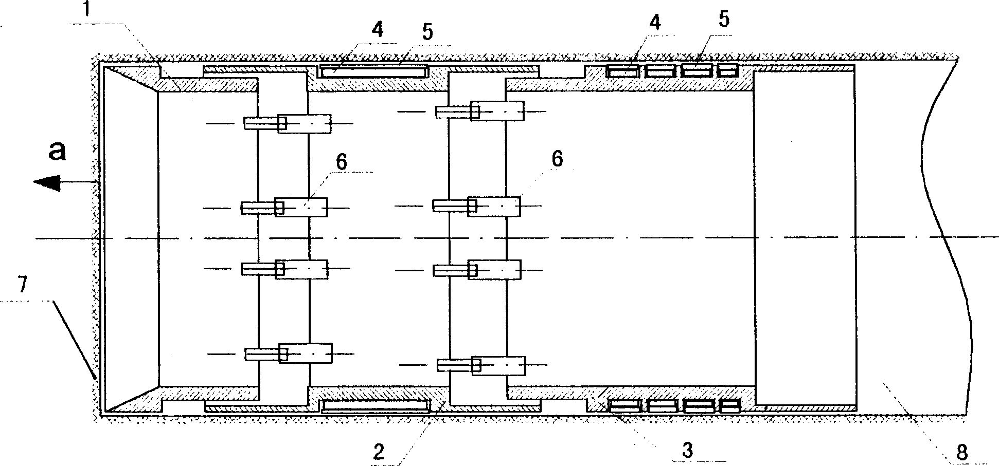
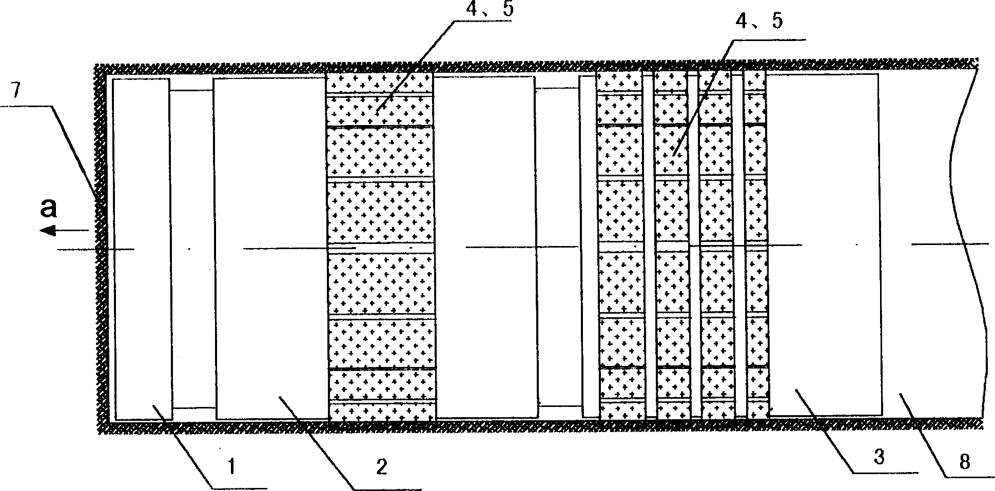
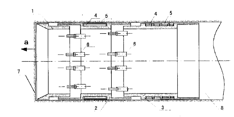
[0020] First dig the working well, lower the tool pipe, lower the tool pipe jack, and push all the tool pipe into the soil layer. When straight-line jacking is required, pressure is applied to the liquid or gas in the hydraulic bag 4 around the tool tube rear section 3 and the hydraulic bag 4 around the tool tube middle section 2 respectively, and the tool tube middle section 2 and the tool tube rear section 3 peripheral The resistance-increasing parts 5 are squeezed tightly with the surrounding soil layer 7 respectively, and hydraulic pressure is applied to the hydraulic cylinder 6 to push the front section 1 of the tool pipe to cut into the soil layer, and loosen the contact between the resistance-increasing part 5 on the middle section 2 of the tool pipe and the soil layer 7, Use the hydraulic cylinder group connecting the front section 1 and the middle section 2 to pull the tool pipe middle section 2 and push the tool pipe middle section 2 forward with the hydraulic cylinde...


PUM


Abstract

The present invention relates to the unopened laying of underground pipeline. The method is that after the tubular tool cut into soil, the resistance increasing part is jacked by the inflated bag around the tool to produce contact force with soil while the hydraulic cylinder inside the tubular tool produce thrust, and the common action of the two forces pushes the tool forwards inside the soil ineither straight line or curved line. The pipe jacking equipment is a telescopic pipe including three embedded sections has annular edge in front end, hydraulic cylinder inside the pipe and resistanceincreasing device around the pipe. The present invention is used in the laying of underground various pipeline.

Description

1. Technical field [0001] The invention relates to a self-driven pipe jacking method and a pipe jacking device for increasing resistance between pipes and soil, and belongs to the field of non-excavation underground pipeline laying construction. 2. Background technology [0002] At present, the conventional pipe jacking construction method is to dig a working well first, lower the tool pipe with blade feet, lower the jack to jack, use the jack to push the tool pipe into the soil layer, lower the pipe joint, connect it to the rear of the tool pipe, and jack it into the ground. Pipe joints, push the tool pipe to cut into the soil layer, and cooperate with manual or mechanical excavation, so repeatedly, push the tool pipe forward in the soil. This pipe jacking construction method has the following disadvantages: First, from the jacking device in the working pit behind the pipeline, through the pipeline that continues to extend with the jacking distance, it is transmitted to the...

Claims


Application Information

Patent Timeline
IPC IPC(8): F16L1/028
Inventor 卢清国
Owner 卢清国
Features
  • Generate Ideas
  • Intellectual Property
  • Life Sciences
  • Materials
  • Tech Scout
  • Unparalleled Data Quality
  • Higher Quality Content
  • 60% Fewer Hallucinations
Learn More