Method and apparatus for patch-clamp measurements on cells

A patch clamp technology, patch clamp technology, applied in the direction of measuring devices, biochemical cleaning devices, biochemical equipment and methods, etc.

Inactive Publication Date: 2007-07-18
フリュイオン ゲゼルシャフト ミット ベシュレンクテル ハフツング
View PDF5 Cites 0 Cited by
  • Summary
  • Abstract
  • Description
  • Claims
  • Application Information

AI Technical Summary

Benefits of technology

This patented technology allows researchers to measure electrical currents by inserting an electrode inside their tiny parts called lamina neapritis that helps them study biological processes like nerve transmission. By modifying certain areas within this area, they may have better understanding about how these changes occur compared to traditional methods used to detect conductive materials. Additionally, there're some advantages over existing techniques: 1) It provides more accurate measurements than previous methods; 2) No tools were necessary during measurement process due to its non-invasiveness and durability against damage caused by external forces while still being effective at removing unwanted samples. Overall, this new technique simplifies the way scientists work through experiments involving studying specific aspects of organisms.

Problems solved by technology

Technological Problem addressed in this patented technical problem is how to create a reliable and efficient way to test various biomedical applications involving tiny particles called microelekmaels.

Method used


Image

  • Method and apparatus for patch-clamp measurements on cells
  • Method and apparatus for patch-clamp measurements on cells
  • Method and apparatus for patch-clamp measurements on cells

Examples


Embodiment Construction

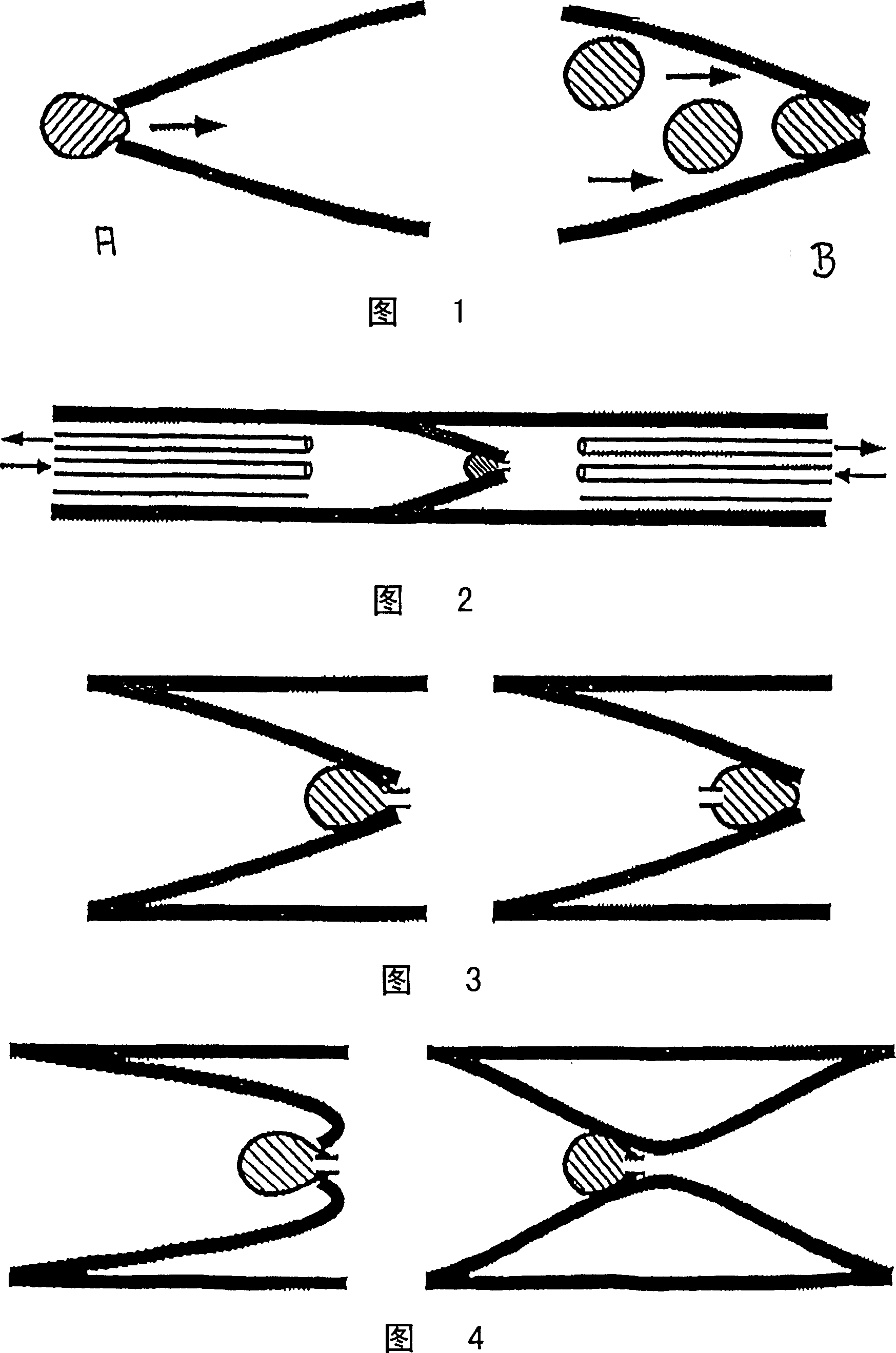
[0090] Figure 1 shows the difference between the method of the present invention and the existing conventional patch clamp technique. Figure 1A shows the binding (sealing) of cells to the tip of a micropipette achieved by the conventional patch clamp method. The seal is formed between the edge of the pipette opening and the cell membrane. Arrows indicate the direction of suction / flow when the pipette tip is pressed against the cells and vacuum is applied to the inside of the pipette. Figure IB shows positioning and sealing of cells by the method of the present invention. Arrows indicate the flow and / or direction of movement of the cells as the suspended cells move towards the tip of the micropipette, for example, in Figure IB there are three suspended cells moving towards the tip of the micropipette. Figure 1B also shows cells forming a seal with the inner wall of the conical pipette. Patch clamp experiments can be performed on the cells. Unlike the state of the art, the m...


PUM


Abstract

The invention shows a method for patch-clamp experiments on cells or similar structures, where at least one cell is inserted into the lumen of a capillary and is positioned inside the capillary so, that a sufficiently tight seal with a resistance exceeding 1, preferably 10 GigaOhm develops between cell membrane and inner surface of the capillary. Along its length said capillary has at least at one position a smaller inner diameter than the outer diameter of said cell. Preferably the cell is inserted and positioned in the capillary by pressure, suction, sedimentation or centrifugation of a suspension or solution containing said cell. An apparatus for performing experiments using this method is described.

Description


Claims


Application Information

Patent Timeline
Owner フリュイオン ゲゼルシャフト ミット ベシュレンクテル ハフツング
Why Eureka
Try Eureka