Centrifuge with aerodynamic rotor and bucket design

a centrifuge and aerodynamic technology, applied in centrifuges and other directions, can solve the problems of increasing drag, generating considerable aerodynamic drag, centrifuge buckets, etc., and achieve the effect of minimal drag over the whole

Active Publication Date: 2008-09-09
DRUCKER COMPANY INC THE
View PDF20 Cites 71 Cited by
  • Summary
  • Abstract
  • Description
  • Claims
  • Application Information

AI Technical Summary

Benefits of technology

[0011]Once the specimen holders are in the retracted position, the subjacent surface of each holder forms an uninterrupted interface about its slot which prevents circulating air from entering the rotor and tube holder assembly. This produces a continuous surface and an aerodynamic assembly that approaches the drag characteristics of a spinning disk. This interface also protects samples from the warmer circulating air and aids in keeping the samples at or near ambient temperatures. Voids near the center of the rotor may optionally be left open, as these locations' overall effect on drag is minimal.

Problems solved by technology

With current swinging bucket rotor designs, the centrifuge buckets are primarily left uncovered by the rotor and generate considerable aerodynamic drag.
This drag increases as the non-aerodynamic features move further away from the axis of rotation.
Thus, significant aerodynamic drag is generated during centrifugation due to air entering the rotor through these voids.
At high speed operations, aerodynamic drag on the rotor becomes increasingly significant.
Significant drawbacks of this design are that cooling or refrigerating the chamber is expensive and prone to malfunction.

Method used


Image

  • Centrifuge with aerodynamic rotor and bucket design
  • Centrifuge with aerodynamic rotor and bucket design
  • Centrifuge with aerodynamic rotor and bucket design

Examples


Embodiment Construction

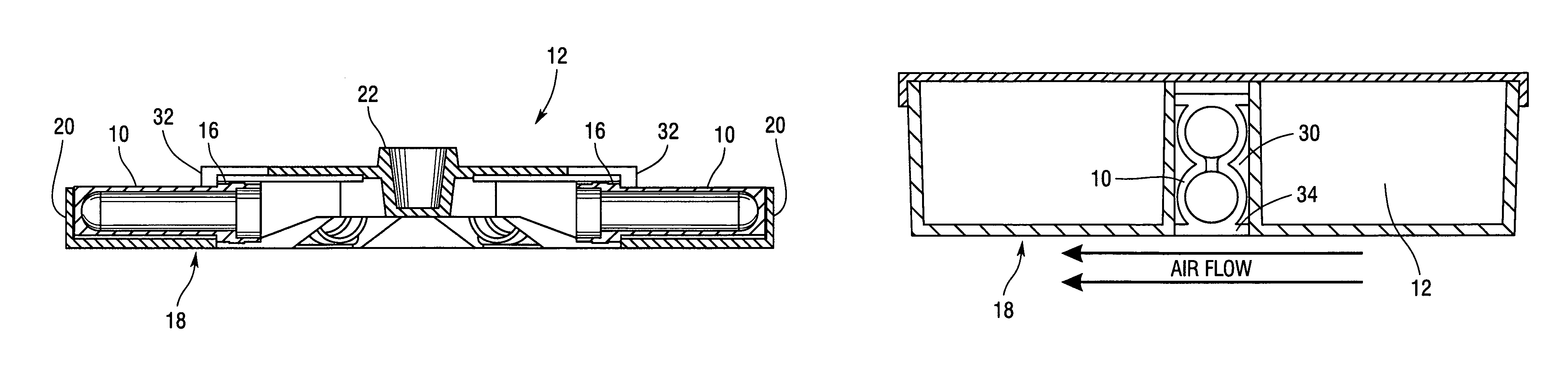
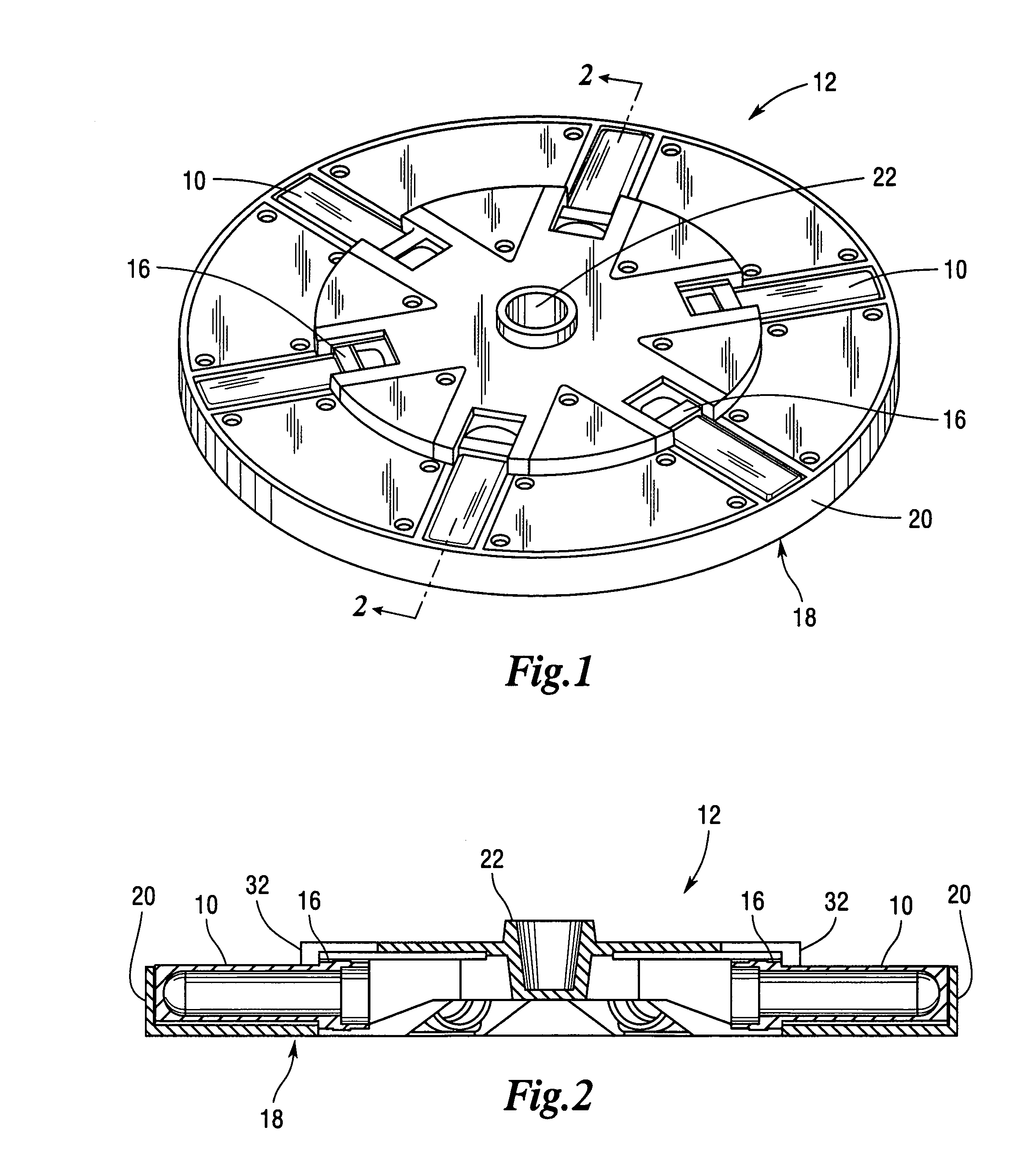
[0021]Referring now to FIGS. 1-8, the present invention comprises a novel design for a fully retractable specimen holder and rotor assembly for use in existing and new centrifuges 14 that are employed, for example, in medical, industrial, and laboratory settings.

[0022]The specimen holder 10 can either hold a specimen or some type of container, such as a test tube, test tube holder, or “bucket” containing a sample to be centrifuged. The rotor 12 and specimen holder assembly of the present invention may incorporate the use of specimen holders 10 having an extended collar 16, rotation pins, or other pivot mechanisms that enable the specimen holder 10 to swing from a resting position to a rotational position. Pivot mechanisms may include, for example, mounting holes, rivets, bolts, trunnions, springs, hinges, and the like.

[0023]The rotor 12 allows for the vertical or near vertical insertion of the specimen holder 10 and its contents. The extended collar 16, rotation pins, or other pivot...


PUM


Abstract

A rotor and specimen holder assembly for producing a relatively low power, low audible level, cool running centrifuge. The centrifuge rotor assembly is designed to enable a specimen holder to retract into the body of the rotor during centrifugation to produce aerodynamic features.

Description

REFERENCE TO RELATED APPLICATIONS[0001]This application claims priority to U.S. Provisional Patent Application No. 60 / 706,935 filed Aug. 10, 2005.BACKGROUND OF THE INVENTION[0002]1. Field of the Invention[0003]The present invention relates to a centrifuge rotor and tube holder design, and more particularly, to a rotor assembly for producing a relatively low power, low audible level, cool running centrifuge.[0004]2. Background Art[0005]Centrifuges are commonly used in medical and biological research for separating and purifying materials of differing densities such as viruses, bacteria, cells, proteins, and other compositions. A centrifuge normally includes a motor, a rotor, and specimen holders capable of spinning up to tens of thousands of revolutions per minute. Specimen holders include, for example, test tubes, test tube holders, or any other means that is suitable for retaining a specimen.[0006]A preparative centrifuge rotor has some means for accepting specimen holders or “buck...

Claims


Application Information

Patent Timeline
Patent Type & Authority Patents(United States)
IPC IPC(8): B04B5/02
CPCB04B5/0421
Inventor MOSCONE, KENNETH J.STOUT, CRAIG
Owner DRUCKER COMPANY INC THE
Why Eureka
Try Eureka