Method for controlling charge-coupled device camera

A technology of charge-coupled devices and charge-coupled cameras, which is applied in the field of CCD cameras, can solve the problems that are not conducive to the miniaturization of cameras, increase the size of CCD cameras, and increase the production cost of CCD cameras.

Inactive Publication Date: 2002-01-23
LG ELECTRONICS INC
View PDF0 Cites 3 Cited by
  • Summary
  • Abstract
  • Description
  • Claims
  • Application Information

AI Technical Summary

Problems solved by technology

[0012] But, considering the trend of miniaturization and cheapness of camera products, when adding glass 22 (that is: "false filter") for adjusting the refractive index of the lens group in the camera lens OLPF21 that directly affects the image, it will increase The production cost of the CCD camera
And, owing to adding glass 2

Method used


Image

  • Method for controlling charge-coupled device camera
  • Method for controlling charge-coupled device camera
  • Method for controlling charge-coupled device camera

Examples


Embodiment Construction

[0024] Next, an embodiment of the present invention will be described with reference to FIGS. 4-7.

[0025] Figure 4A is a schematic sectional view of a lens unit to describe the focal length when using an OLPF (Optical Low Pass Filter).

[0026] Figure 4B is a schematic cross-sectional view of a lens unit depicting the focal length with and without dummy glass.

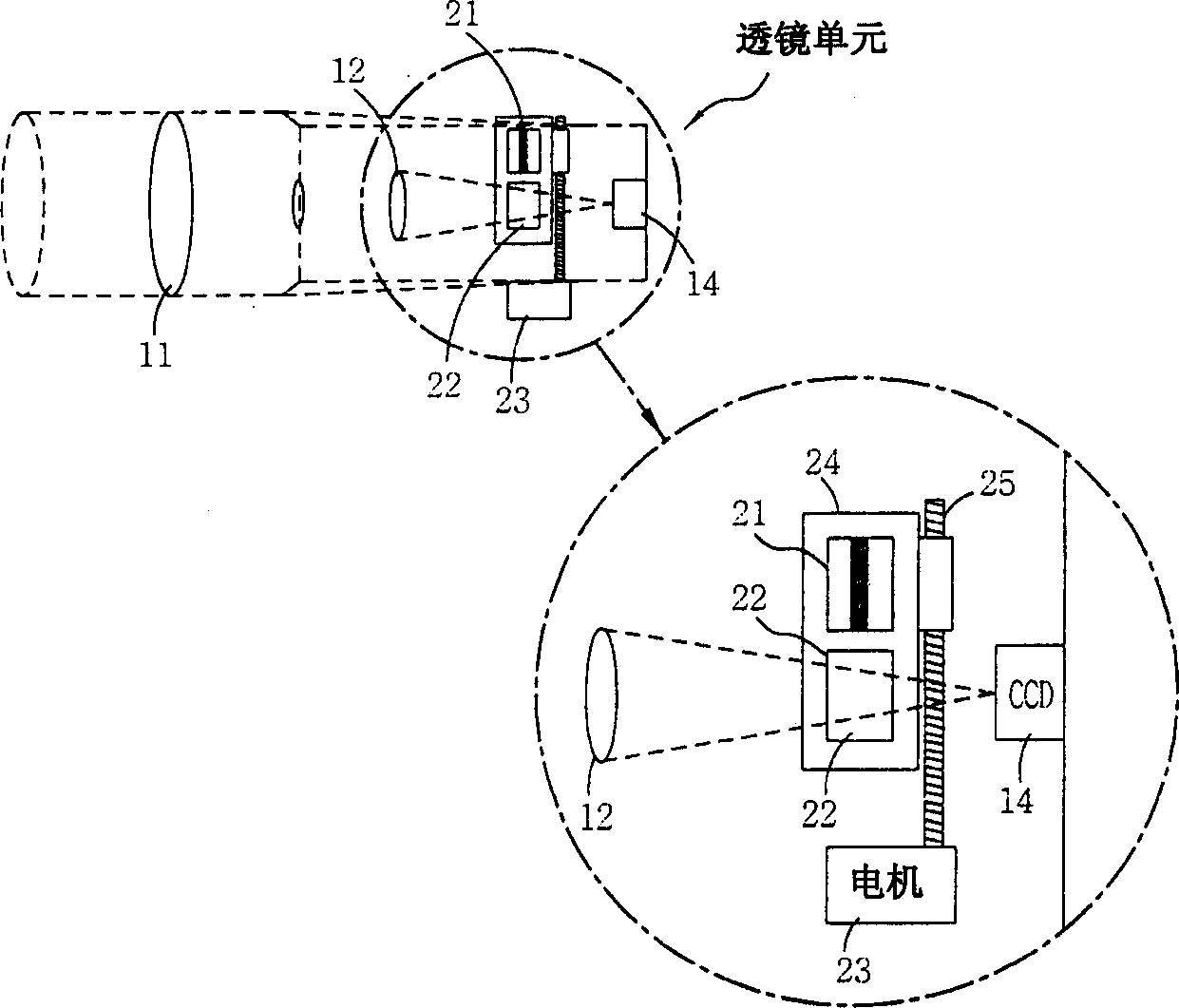
[0027] First, since the light passing through the zoom lens 31 and the focus lens 32 is refracted when passing through the OLPF (Optical Low Pass Filter) 33, the incident angle of the light is changed, and the focal length of the lens group becomes longer due to the change in the incident angle . Here, the OLPF33 is placed on a movable base plate 41, and the OLPF33 is mechanically moved into or out of the optical path of the lens group according to the shooting mode of the CCD (charge-coupled device) camera, such as day mode or night mode.

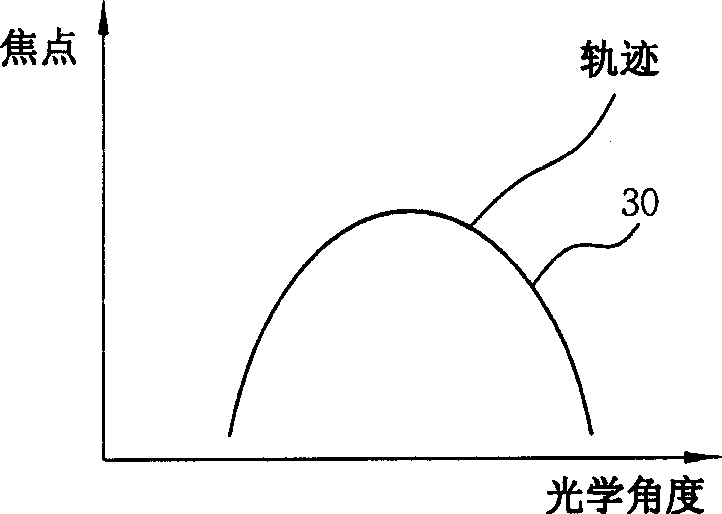
[0028] Therefore, when determining the control trajectories of the focu...


PUM


Abstract

In a control method of a CCD (Charge-Coupled Device) camera, control traces for a zoom lens and a focus lens of the camera are adjusted in accordance with pre-stored trace data so as to compensate a focus error in accordance with the use or not of an OLPF (Optical Low Pass Filter) in automatic adjustment of the focus lens and the zoom lens. Accordingly, because a photographing mode can be converted into a daytime mode or a nighttime mode without changing a lens unit, the facility of user can increase, the price can be reduced and miniaturization of a CCD camera can be performed by eliminating a dummy glass for adjusting a refractive index when not using the OLPF.

Description

field of invention [0001] The present invention relates to a kind of CCD (charge-coupled device) camera, relate in particular to a kind of control method of CCD camera, this method can be by adjusting the control locus of zoom lens and focus lens in the automatic adjustment of CCD camera in focus state and zoom state. Compensates for focus errors caused by using or not using OLPF (Optical Low Pass Filter). Background technique [0002] FIG. 1 is a cross-sectional view of the internal structure of a typical lens unit in the prior art. [0003] As shown in Figure 1, the integral lens unit in the prior art comprises: zoom lens 11, is used for imaging target imaging to make it zoom in or out; Focus lens 12, is used for adjusting the object image focus OLPF ( Optical low-pass filter) 13, is used for filtering the formed image so that it only passes through the light visible to the human eye by blocking infrared rays in the process of shooting the shooting target incident on the ...

Claims


Application Information

Patent Timeline
IPC IPC(8): G03B7/00G02B7/28H04N5/225
CPCG02B7/28H04N5/2254H04N5/23296H04N23/55H04N23/60H04N23/69G03B7/00
Inventor 朴世雄
Owner LG ELECTRONICS INC
Why Eureka
Try Eureka