Closet with spraying device
A technology of spray device and toilet, applied in the international patent classification E03D "urinal with flushing equipment, improvement in disinfection, toilet in the field of cleaning, can solve the problem of difficult control of concentration, large amount of medicine, backward disinfection methods, etc. question
- Summary
- Abstract
- Description
- Claims
- Application Information
AI Technical Summary
Problems solved by technology
Method used
Image
Examples
Embodiment 1
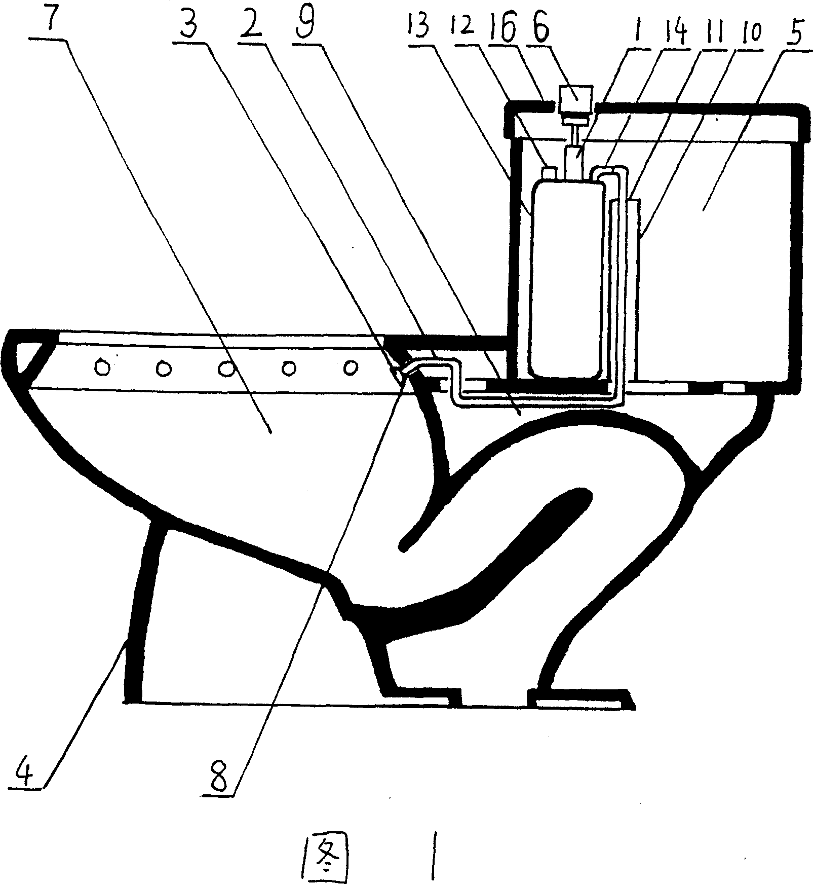
[0007] Embodiment 1: As shown in Figure 1, a toilet with a spraying device includes a base 4, a water tank 5, a urinal 7, a flushing hole 8, a drain pipe 9, and an overflow prevention port 11. The special place is: one end of the conduit 2 is connected with the shower nozzle 3, and the other end is penetrated at the flushing hole 8 in the urinal 7, and through the drain pipe 9 connecting the water tank 5 and the flushing hole 8, the water tank 5 The anti-overflow pipe 10 and the anti-overflow port 11 enter the water tank 5, and the shower nozzle 3 is installed at the flush hole 8 in the urinal 7. The pressure injection device 1 with the liquid medicine cylinder 13 is installed in the water tank 5 without affecting the position of the original parts in the water tank 5. The injection pipe 14 of the pressure injection device 1 is connected with the conduit 2, and the pressure injection device 1 and the liquid medicine cylinder are injected. The medicine port 12 should be arrange...
Embodiment 2
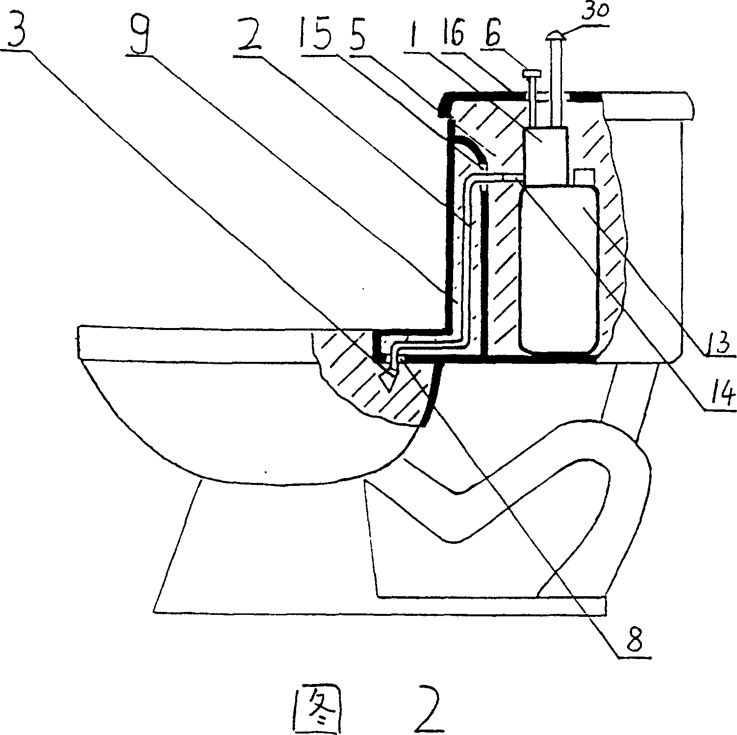
[0017] Embodiment 2: As shown in Figure 2, its working principle, basic composition, connection and installation method are similar to those of Embodiment 1, the difference is that it is connected to the nozzle 3 and penetrated by the flushing hole 8, and passes through the drain pipe 9 The conduit 2 enters the water tank 5 by the water tank upper outlet 15, and is connected with the injection pipe 14 of the pressure injection device 1 with the liquid medicine cartridge 13.
[0018] In this embodiment, the pressure injection device 1 with the liquid medicine cartridge 13 is referred to, and its pressure comes from a pump. The device 1 is composed of a manual piston air pump and related components. In practice, reference can be made to the relevant structure of a manual compression sprayer , this type of sprayer is the prior art, so its principle and working process will not be described in detail in this article.
[0019] Present embodiment also needs on the water tank lid 16 ...
Embodiment 3
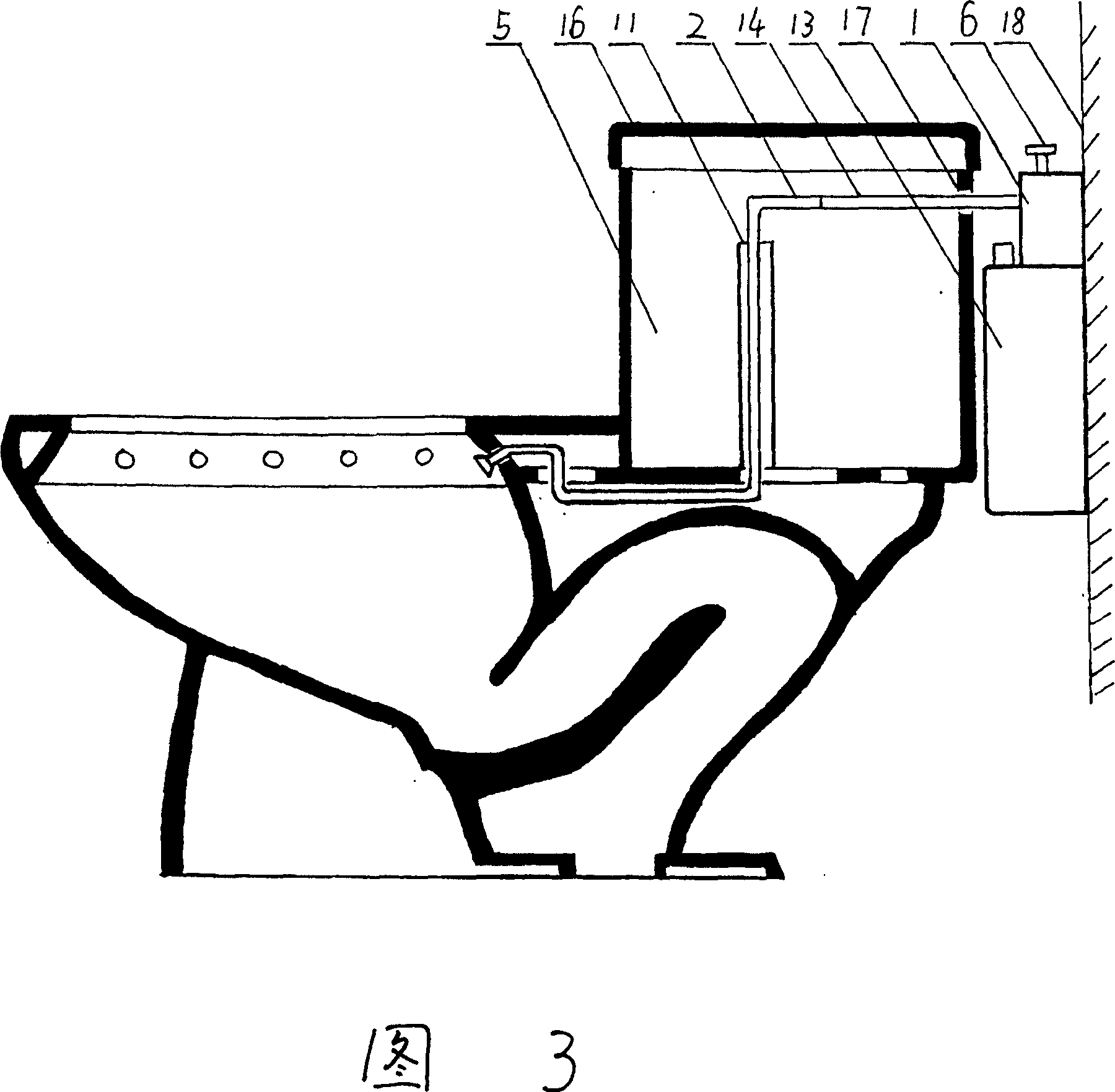
[0020] Embodiment 3: As shown in Figure 3, its working principle, basic composition, connection, and installation method are similar to Embodiment 1, the difference is that the pressure injection device 1 with the liquid medicine cartridge 13 is installed on the wall behind the water tank 5 On 18, perforate 17 on water tank 5 walls, its diameter ≥ φ 3mm, ≤ φ 5mm, the lower edge level of hole 17 is slightly higher than the level of anti-overflow port 11, to prevent the water in the water tank 5 from flowing out. The injection pipe 14 of the pressure injection device 1 is penetrated into the water tank 5 by the hole 17, and is connected with the conduit 2 while not affecting the original parts in the water tank 5 . Because the spray key 6 is outside the water tank 5, it is not necessary to perforate the water tank cover 16.
[0021] In this embodiment, the pressure injection device 1 with the liquid medicine cartridge 13 has its pressure sourced from a pump, and the device 1 is ...
PUM
 Abstract
Description
Claims
Application Information
 - R&D
- Intellectual Property
- Life Sciences
- Materials
- Tech Scout
- Unparalleled Data Quality
- Higher Quality Content
- 60% Fewer Hallucinations
Browse by: Latest US Patents, China's latest patents, Technical Efficacy Thesaurus, Application Domain, Technology Topic, Popular Technical Reports.
© 2025 PatSnap. All rights reserved.Legal|Privacy policy|Modern Slavery Act Transparency Statement|Sitemap|About US| Contact US: help@patsnap.com


