
Installation distributing tool and multi-band lifting-clamping device

A clamping device and clamping device technology, applied in elevators, transportation and packaging, lifting equipment in mines, etc., can solve problems such as damage to steel strips, and achieve the effect of eliminating winding problems, reducing costs and saving installation time.

Inactive Publication Date: 2002-01-30
OTIS ELEVATOR CO
View PDF0 Cites 11 Cited by
  • Summary
  • Abstract
  • Description
  • Claims
  • Application Information

AI Technical Summary

Problems solved by technology

This wrapping can damage the strip

Method used


Image

  • Installation distributing tool and multi-band lifting-clamping device
  • Installation distributing tool and multi-band lifting-clamping device
  • Installation distributing tool and multi-band lifting-clamping device

Examples


Embodiment Construction

[0024] DETAILED DESCRIPTION OF THE PREFERRED EMBODIMENT

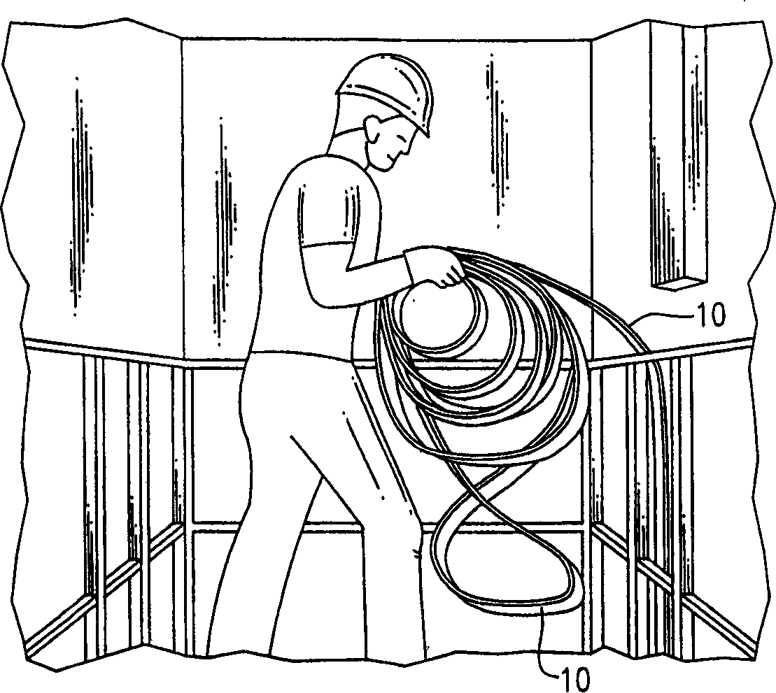
[0025] Referring to Figure 1, (Prior Art) As previously stated, Otis elevators have introduced into the technical field of elevator systems coated steel belts 10 that can be used as tension members. These new belts 10 are stronger and more flexible than conventional steel cables which have many advantages. Conventional methods for installing steel cables can also be used for installing the steel belt 10 . In particular, as shown in Figure 1, the steel belt is fed independently under the elevator shaft around one pulley and then over a second pulley, the ends of the belt being fastened to the At the second pulley.

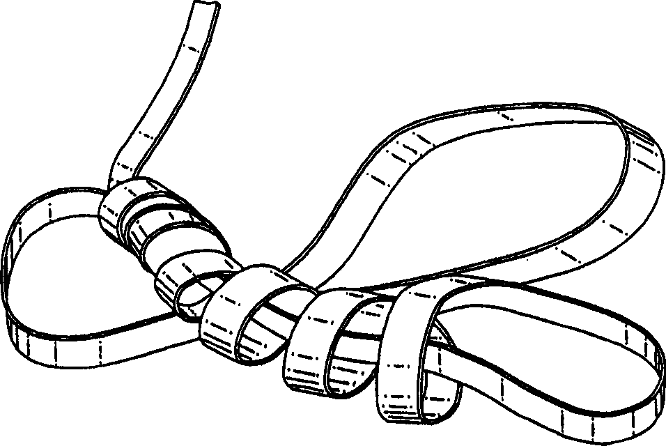
[0026] However, when such a new coated steel strip 10 is installed using conventional methods, the strip 10 is wound as shown in FIG. 2 (prior art).

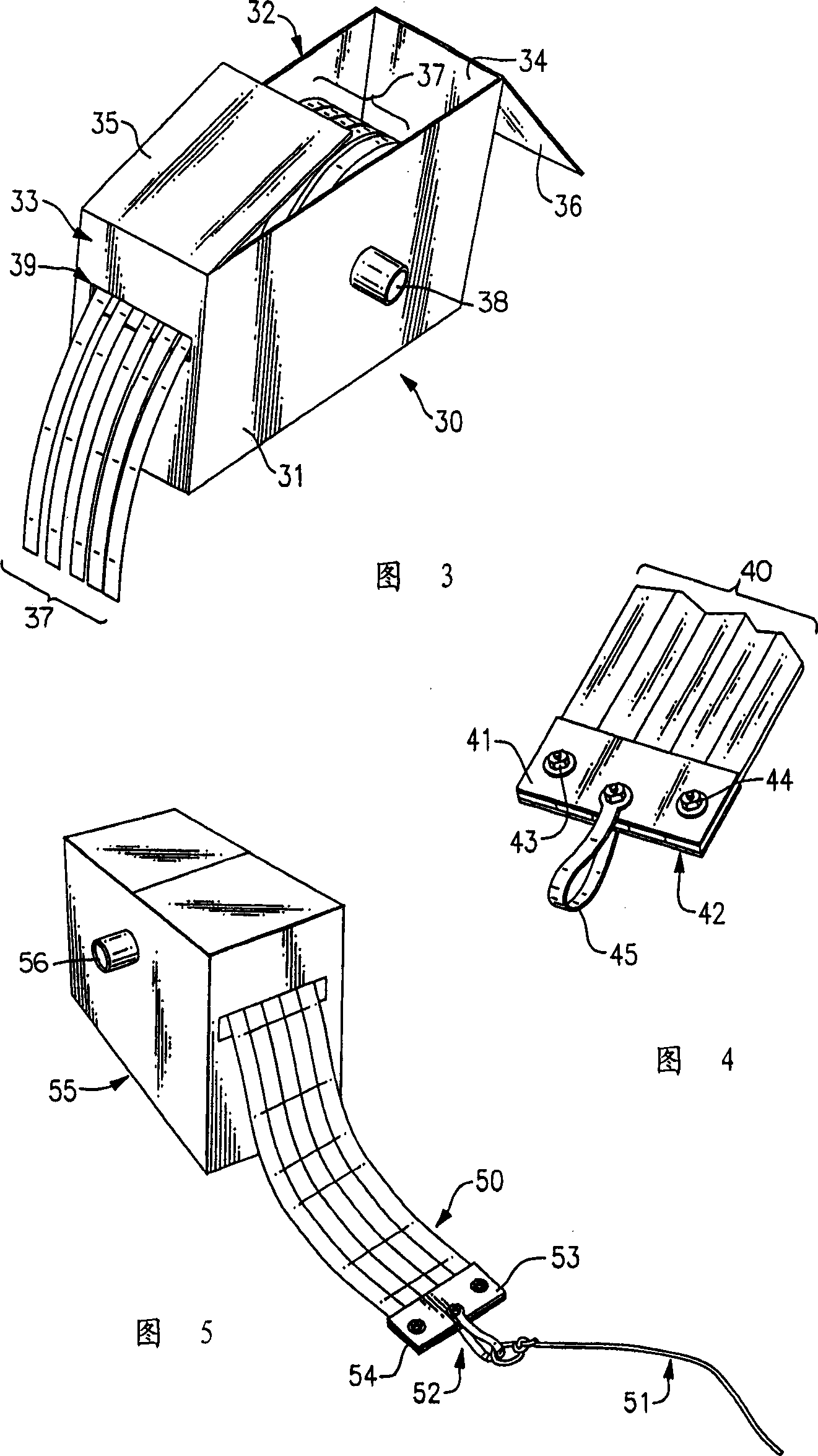
[0027] As shown in Figure 3, the box-type container includes a generally rectangular floor (not shown). A generally rectangular first side panel 31 and a g...


PUM


Abstract

A method and apparatus for installing a plurality of coated steel belts as tension members for an elevator system. A dispenser is employed that retains a plurality of rolled steel belts aligned vertically in said dispenser. An axel passing through the side walls of the dispenser and the centers of the steel belts rolls contained therein rotatably supports the steel belt rolls. When employing the disclosed method, equal lengths of the belts are pulled from the dispenser and clamped between two metal plates. A guide is then connected to the clamped plates which is used to feed the secured coated steel belts down the elevator shaft, around the sheave mechanism and back up the elevator shelf. The center core of the dispenser allows for the even systematic dispensing of steel belts so that equal lengths of the steel belts are fed simultaneous throughout the elevator system.

Description

field of invention [0001] The present invention relates to a method for installing a plurality of coated steel belts as tension members of an elevator system. Background technique [0002] A conventional traction elevator system consists of a car, a counterweight, two or more cables interconnecting the cabin and counterweight, a traction sheave for moving the cables and a traction sheave for moving the cables. A machine that pulls pulleys. Although this design has proven reliable and cost-effective over the years, the cables in such a system have a limited useful life. The limitation of steel cable service life is caused by several factors. For example, in order to increase the friction between the steel cable and the pulley, the wrapping angle of the steel cable is increased or grooves are formed on the pulley. These two methods will increase the wear of the wire rope and / or increase the pressure of the wire rope. Another limitation associated with conventional steel ca...

Claims


Application Information

Patent Timeline
Patent Type & Authority Applications(China)
IPC IPC(8): B66B7/06B66B19/00
CPCB66B7/062B66B19/00B66B19/02
Inventor T·E·格拉西
Owner OTIS ELEVATOR CO
Learn More