

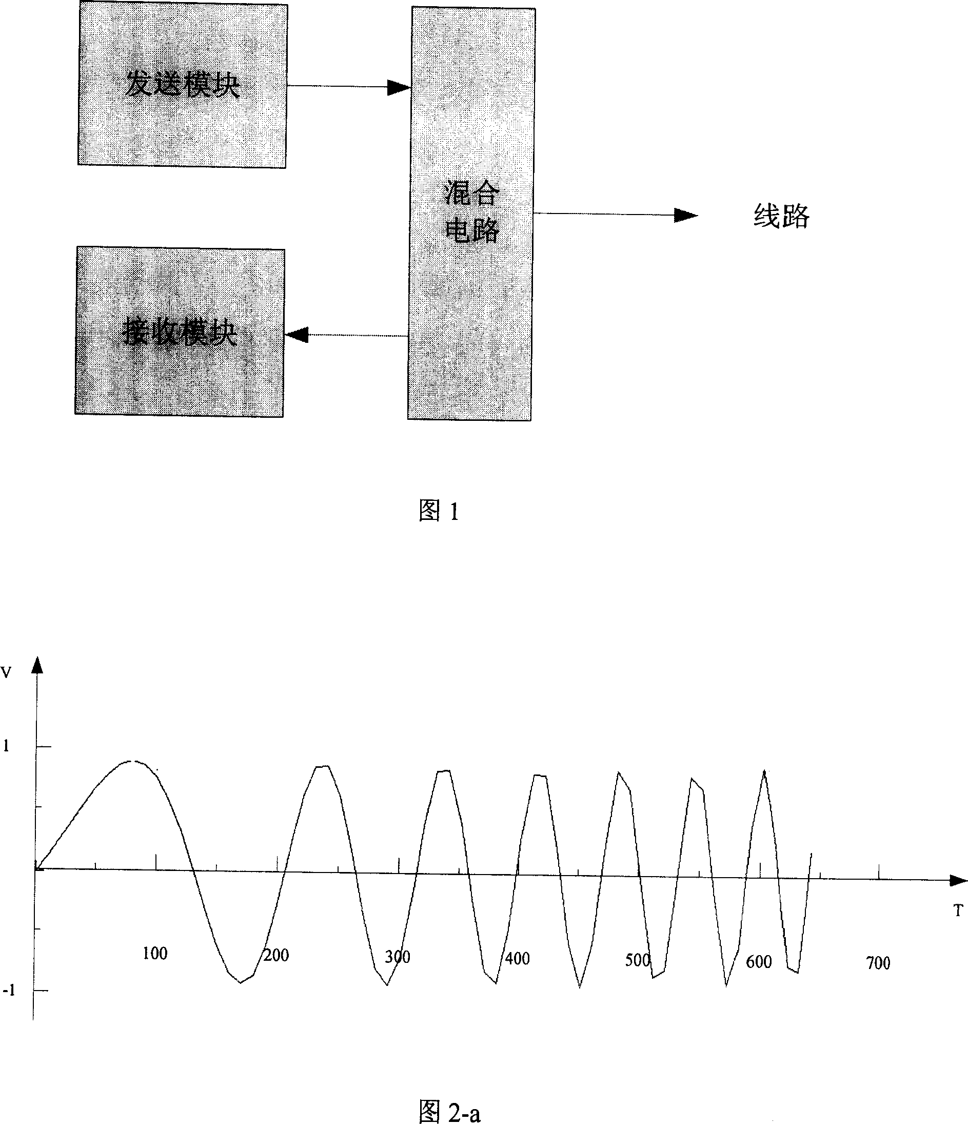
Method for testing network transmission line using time-domain signal
A network transmission and time-domain signal technology, applied in the transmission system, digital transmission system, data exchange network, etc., can solve the problems of poor anti-interference ability, poor resolution of continuous impedance transformation points, long test time, etc., to achieve The effect of strong resolution and strong anti-interference ability
- Summary
- Abstract
- Description
- Claims
- Application Information
AI Technical Summary
Problems solved by technology
Method used
Image

Examples
Embodiment Construction
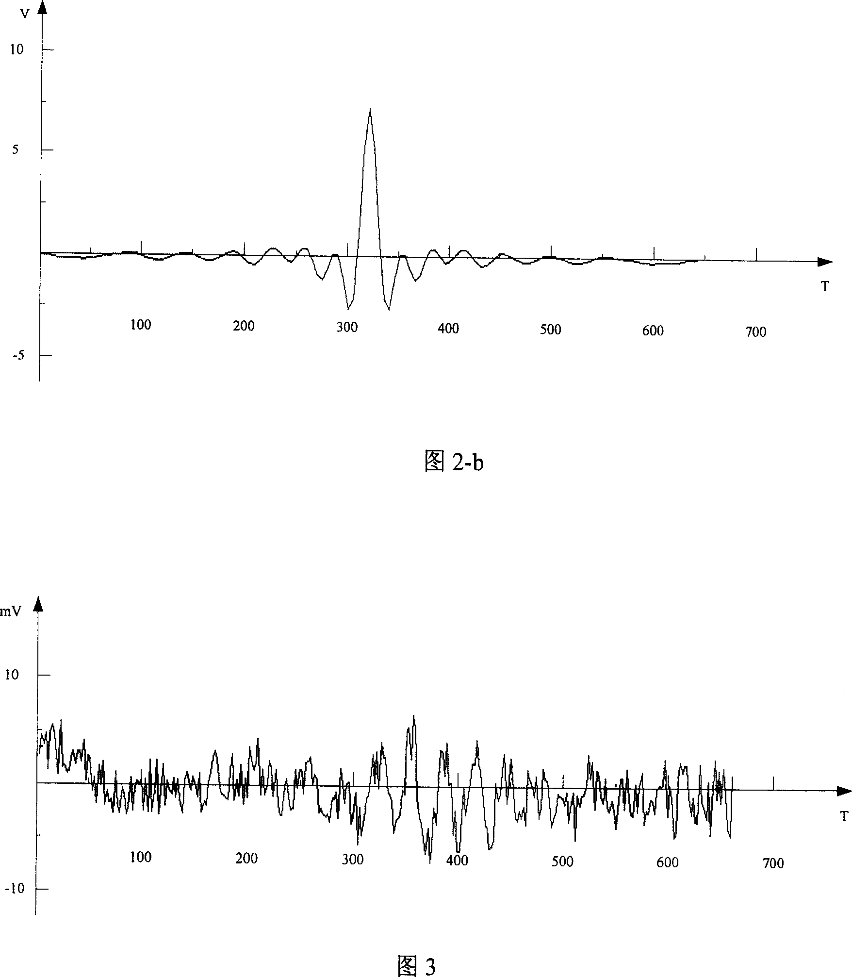
[0041] 1. The CHIRP signal is used as the original sending signal and the basic algorithm principle description:
[0042] The continuous impedance transformation point can be correctly distinguished by the TDR test method, but if the distance between the two impedance transformation points is 200 meters, then the maximum length of the original transmitted signal is 1us when the time aliasing of the two reflected signals does not occur. For example, if a 1MHz sinusoidal signal is used, only one cycle length can be used. Even if the echo signal is received at the receiving end, it is difficult to correctly distinguish the continuous impedance transformation point.
[0043] The CHIRP signal is used as the sending signal for the TDR test of the network transmission line. Referring to Figure 2, the autocorrelation of the CHIRP signal is relatively strong, and the time compression of more than 1 / 16 can be achieved on the user twisted pair line. The waveform reflected from the line i...
PUM
 Abstract
Description
Claims
Application Information