Ball valve

A technology for ball valves and spherical valve bodies, which is applied in the direction of valve devices, cocks including cut-off devices, engine components, etc., which can solve the problems of inflexible opening and closing of ball valves, leakage service life, etc. flexible effects

Inactive Publication Date: 2002-02-27
甘靖
View PDF1 Cites 9 Cited by
  • Summary
  • Abstract
  • Description
  • Claims
  • Application Information

AI Technical Summary

Problems solved by technology

[0003] In order to solve the problems of inflexible opening and closing, easy leakage and short service life of the existing ball valves mentioned above, the present invention provides a ball valve with a novel and unique structure.

Method used


Image

  • Ball valve
  • Ball valve
  • Ball valve

Examples


Embodiment Construction

[0009] Specific embodiments of the ball valve of the present invention will be described in detail below with reference to the accompanying drawings.

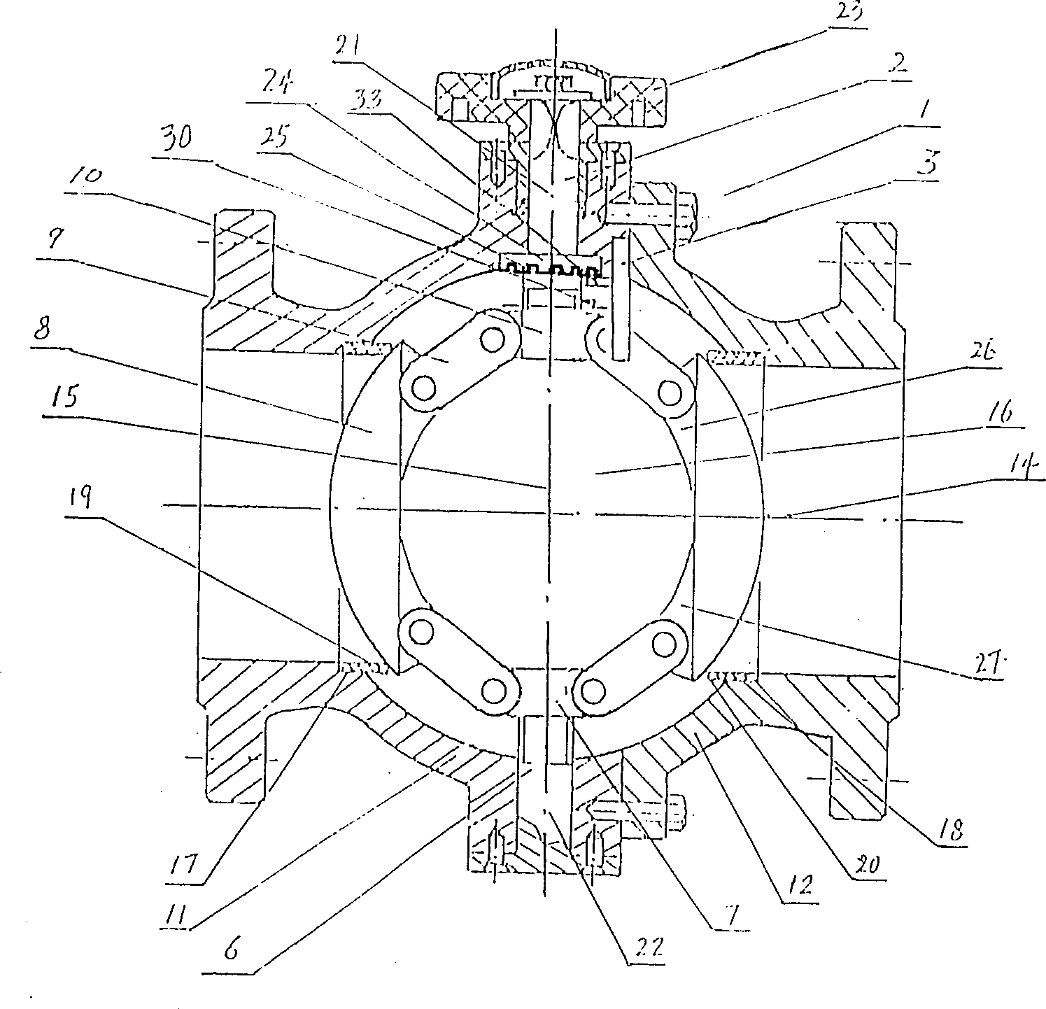
[0010] Such as figure 1 As shown, the ball valve of the present invention has two substantially hemispherical half shells 11 and 12, which are fixedly connected by bolts to form a hollow spherical valve body 1.

[0011] The spherical valve body 1 has a horizontal central channel 14 , a vertical central hole 15 from top to bottom and a valve chamber 16 .

[0012] The two half-shells 11 and 12 respectively have annular valve seats 17 and 18 on the horizontal central channel of the spherical valve body 1, on which a sealing member 19 and 20 is mounted respectively.

[0013] The vertical central hole 15 includes a vertical central hole 21 at the top of the spherical valve body 1 and a vertical central hole 22 at the bottom of the spherical valve body 1 .

[0014] A valve stem 2 is rotatably installed in the vertical central hole ...


PUM


Abstract

The present invention relates to a ball valve, its valve rod and left-hand screw thread end of its uspporting shaft are respectively equipped with an upper nut and a lower nut which respectively possess a pair of symmetrical lugs, and two lugs positioned on same side of said upper nut and lower nut are respectively hinge-connected with one end of one link joint, and another end of the link joint is hinge-connected with half-valve core with spherical external surface of said side, and the upper end surface of upper nut possesses a ring groove in which can open-ended spring is fixedly mounted, a positioing pin is inserted into valve cavity, and on the positioning pin a press plate is fixedly mounted. The opening and closing processes of said valve are implemented by means of separation and contact of two semi-spherical valve cores and valve seat seal component, they do not produce friction, so that said ball valve has no leakage and its service life is long as compared with existent ball valve.

Description

(1) Technical field [0001] The invention relates to a ball valve. (2) Background technology [0002] Chinese utility model patent ZL97250196.9 discloses a ball valve. It has a hollow valve body. There is a longitudinal center hole at one end of the valve body, and a cylindrical valve cover with a longitudinal center hole is installed at the other end of the valve body, thereby forming a valve chamber in the valve body. A valve ball having a longitudinal center hole is housed in the valve chamber. A valve seat is respectively formed on the facing parts of the valve body and the valve cover located in the valve chamber, and a sealing member is installed on each valve seat. There is a transverse hole leading into the valve chamber on the valve body. There is a valve stem in the transverse hole. One end of the valve stem is movably connected to the valve ball located in the valve chamber, and the other end is fixedly connected to the handle located outside the valve chamber...

Claims


Application Information

Patent Timeline
Patent Type & Authority Applications(China)
IPC IPC(8): F16K5/06
Inventor 甘靖
Owner 甘靖
Why Eureka
Try Eureka