Valve shaft sealing device

A sealing device and valve shaft technology, applied in shaft sealing, valve device, valve details and other directions, can solve the problems of pipeline pressure rise, pipeline circulation medium leakage, etc., to achieve small valve opening and closing torque, good sealing performance, and contact area. small effect

Inactive Publication Date: 2020-06-30
HUBEI TAIHE PETROCHEM EQUIP
View PDF0 Cites 1 Cited by
  • Summary
  • Abstract
  • Description
  • Claims
  • Application Information

AI Technical Summary

Problems solved by technology

[0003] The technical problem to be solved by the present invention is to provide a valve shaft sealing device, which is used to solve the problem that the pipeline pressure rises and the medium in the pipeline leaks from the valve shaft

Method used


Image

  • Valve shaft sealing device
  • Valve shaft sealing device
  • Valve shaft sealing device

Examples


Embodiment Construction

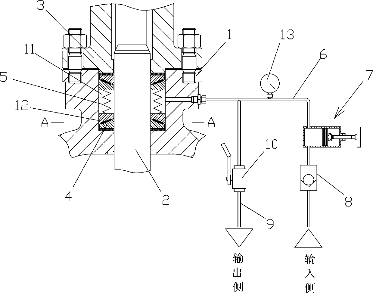
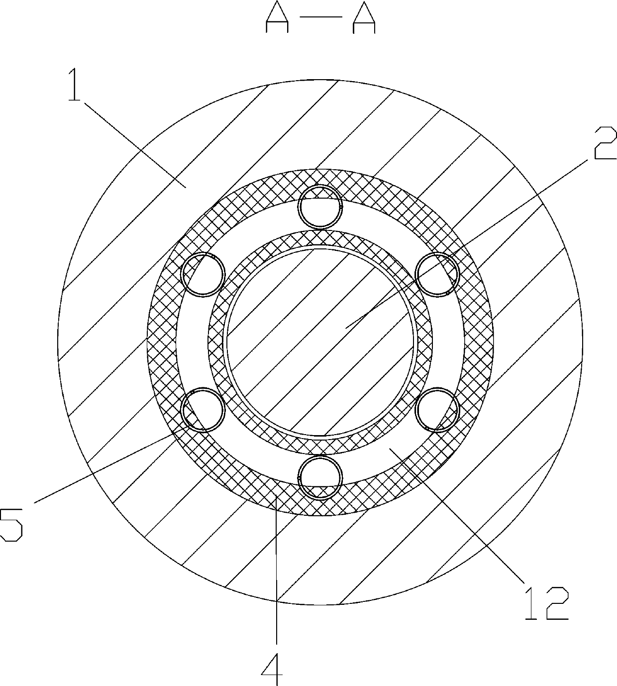
[0014] Such as figure 1 with 2 As shown, a valve shaft sealing device includes a valve body 1, a valve shaft 2 and a gland 3, an annular groove 11 is arranged in the valve body 1 around the valve shaft 2, and the gland 3 seals the upper opening of the groove 11 , There are two sets of expansion assemblies in the slot 11, the two sets of expansion assemblies pass through a plurality of springs 5, and each spring 5 is evenly distributed around the axis of the valve shaft 2, and the springs 5 ​​push the two sets of expansion assemblies against the gland 3 and the The bottom surface of the cut groove 11, the cut groove 11 is connected to the input end of the valve body 1 through the liquid inlet pipe 6; the expansion assembly includes two rubber rings 4, and the end faces of the two rubber rings 4 in contact with each other are inclined surfaces.

[0015] The working principle of the present invention is: when the pressure of the pipeline where the valve is installed is at normal...


PUM


Abstract

The invention discloses a valve shaft sealing device. The valve shaft sealing device comprises a valve body, a valve shaft and a gland; an annular cutting groove is formed in the valve body around thevalve shaft, an opening in the upper end of the cutting groove is blocked by the gland, two expansion assemblies are arranged in the cutting groove, the two expansion assemblies are connected with aplurality of springs, and the springs push the two expansion assemblies to abut against the gland and the bottom face of the cutting groove correspondingly; the cutting groove communicates with the input end of the valve body through a liquid inlet pipe; each expansion assembly comprises two rubber rings, and the end faces, making contact with each other, of the two rubber rings are inclined faces. The valve shaft sealing device is used for solving the problems that the pipeline pressure rises and pipeline distribution medium leaks from the valve shaft.

Description

technical field [0001] The invention relates to a valve shaft sealing device. Background technique [0002] At present, the valve shaft is generally sealed with packing, such as oil-immersed packing, graphite, and rubber combined sealing packing. However, in practical applications, when adjusting the packing gland, the pipeline is generally under normal pressure, and workers load the sealing packing through the gland. Stop loading the gland until the pipeline flow medium can no longer leak from the valve shaft; do not press the gland too tightly, because too tight compression of the packing gland will cause the friction force exerted by the sealing packing on the gland If it is too large, it will make it difficult for the valve shaft to rotate or move axially, the valve opening torque will increase, and the labor intensity of workers will increase; The sudden start and stop of the pump will cause the pressure of the pipeline to rise instantaneously, and the flowing medium i...

Claims


Application Information

Patent Timeline
Patent Type & Authority Applications(China)
IPC IPC(8): F16K41/04F16K27/08
CPCF16K27/08F16K41/04
Inventor 章文忠
Owner HUBEI TAIHE PETROCHEM EQUIP
Why Eureka
Try Eureka