
Ceramic slide valve

A technology of ceramic valve seat and ceramic valve core, which is applied in the direction of sliding valves, valve devices, engine components, etc., can solve problems such as poor sealing performance, flow channel erosion, and damage to the sealing surface of valve seats, so as to improve processing technology, Avoid erosion and cavitation and improve service life

Pending Publication Date: 2018-09-14
YANTAI KINGWAY SCI & TECH
View PDF7 Cites 1 Cited by
  • Summary
  • Abstract
  • Description
  • Claims
  • Application Information

AI Technical Summary

Problems solved by technology

[0004] (1) During the opening and closing process of the ball valve, the medium easily enters the valve cavity and accumulates in the valve cavity; when the temperature of the medium decreases, some medium will solidify and lock the opening and closing parts, so it is easy to cause serious consequences such as valve jamming
[0005] (2) When the high-hardness granular medium flows in the pipeline at high speed, it is easy to cause the sealing surface of the valve seat to be damaged or the spray coating on the surface of the sphere to fall off, which will affect the sealing effect of the valve. In severe cases, it will cause the valve sealing to fail
[0006] After the slide valve has been in operation for a period of time, the valve is jammed because the cavity is filled with materials; the wear between the slide plate and the splint is serious, and in the above system, due to the physical and chemical characteristics of the fluid, some valves often have valve trim or The flow channel behind the valve seat is severely damaged by erosion and cavitation, which in turn causes the failure of the valve and even the entire delivery system to operate normally
[0007] Butterfly valves, gate valves, flapper valves, etc., not only have poor sealing performance, but also because of the serious bias flow of the medium fluid, it is very easy to wash the flow channel, resulting in frequent replacement of the pipeline

Method used


Image

  • Ceramic slide valve
  • Ceramic slide valve
  • Ceramic slide valve

Examples


Embodiment Construction

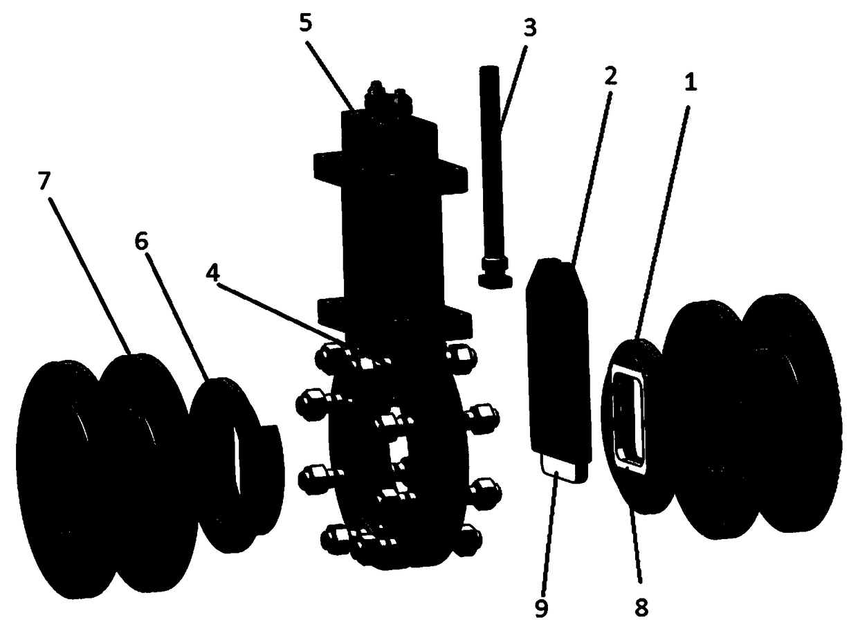
[0030] Such as figure 1 As shown, a ceramic slide valve includes a disc valve seat 1 and a slider 2, a valve stem 3, a valve body 4, an upper platform 5, a valve inner lining 6, and a flange 7; There is a valve inner lining 6; the lower end of the valve stem 3 is connected with the upper end of the slider 2; Moving up and down, it forms a plane seal with the edge of the flow channel hole of the disc valve seat 1, and realizes throttling, opening and closing of the fluid.

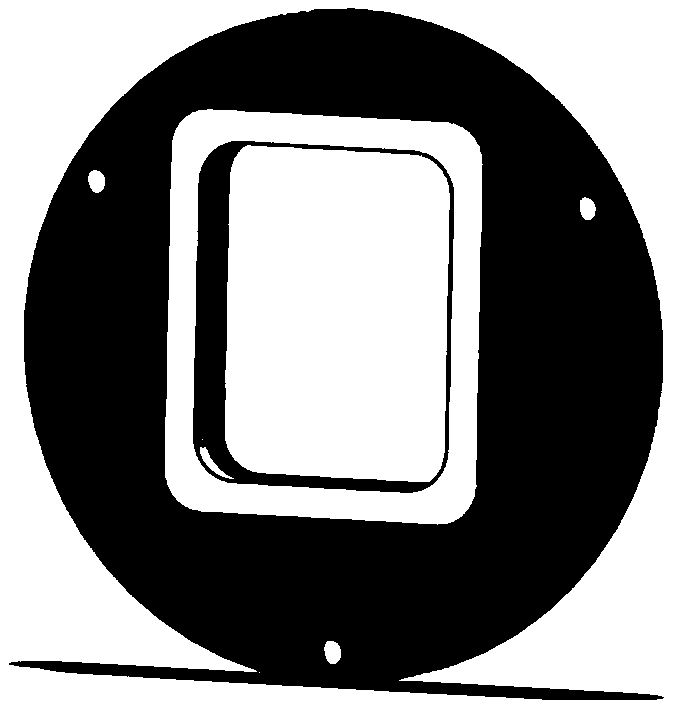
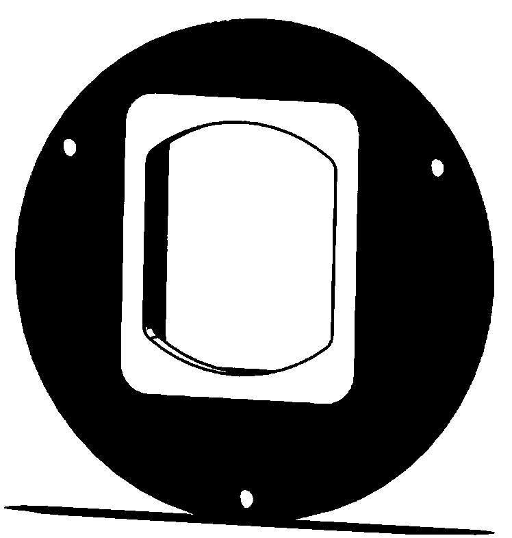
[0031] The disc valve seat 1 is in the shape of a disc and is fixed on the valve body 4 . The disc valve seat 1 adopts metal inlaid ceramic valve seat 8, and the edge of the flow channel hole and the main sealing surface of the disc valve seat 1 are all made of structural ceramic materials.

[0032] The combination of ceramic and metal is mechanical locking, gluing or mechanical gluing combination; the sealing surface of the flow channel hole is made of ceramic wear-resistant material.

[0033] The up and...


PUM


Abstract

The invention discloses a ceramic slide valve. The ceramic slide valve comprises a round plate valve seat (1), a slide block (2), a valve rod (3), a valve body (4), an upper platform (5), a valve bodyliner (6) and a flange (7); the valve body liner (6) is arranged in the valve body (4); the lower end of the valve rod (3) is connected with the upper end of the slide block (2) in a matched mode; and the slide block (2) drives a ceramic valve core (9) to move up and down on one side of a ceramic valve seat (8) inlaid in the round plate valve seat (1), and is in plain sealing with the edge of a runner hole of the round plate valve seat (1), and throttling, starting and stopping of fluid are achieved.

Description

technical field [0001] The invention relates to the technical field of valves, in particular to a ceramic slide valve. Background technique [0002] In coal chemical industry, silicon chemical industry, mining metallurgy, electric power environmental protection and other industries, there are a large number of gas-solid, liquid-solid, gas-liquid-solid three-phase media, especially in the case of hard particle media, most of which are currently used are hard-sealed ball valves, Butterfly valves, slide valves, gate valves, flapper valves and other valves more or less have the problems of short service life and difficult maintenance, especially in some strong erosion conditions that require strict sealing, but there are viscous media, Where it is easy to agglomerate, scale, crystallize or contain large particles, not only the erosion is serious, but also various valves are often blocked and stuck. [0003] Taking the hard-sealed ball valve most used under these working conditi...

Claims


Application Information

Patent Timeline
Patent Type & Authority Applications(China)
IPC IPC(8): F16K3/02F16K3/314F16K3/32
CPCF16K3/0236F16K3/314F16K3/32
Inventor 金浩军姜雅周
Owner YANTAI KINGWAY SCI & TECH
Learn More