Apparatus for air treatment and transportation of a material

A technology of air and conveying direction, which is applied in the field of equipment used for material air treatment and conveying, which can solve the problems of expensive manufacturing and difficult cleaning of the device, and achieve the effect of cheap manufacturing and maintenance and easy cleaning

Inactive Publication Date: 2002-03-06
鲁宾·拉森
View PDF4 Cites 3 Cited by
  • Summary
  • Abstract
  • Description
  • Claims
  • Application Information

AI Technical Summary

Problems solved by technology

[0011] In principle, the methods and devices described above must serve their purpose well, but these devices are expensive to manufacture, require maintenance and are difficult to clean

Method used


Image

  • Apparatus for air treatment and transportation of a material
  • Apparatus for air treatment and transportation of a material
  • Apparatus for air treatment and transportation of a material

Examples


Embodiment Construction

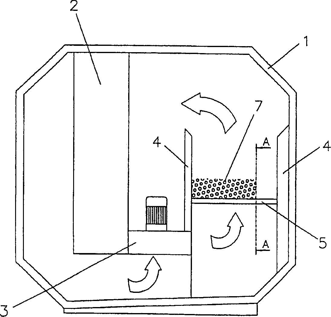
[0029] exist figure 1 In the arrangement shown, the insulating housing is identified as 1 . The material 7 passing through the device, ie in the example the food to be frozen, passes through the device as a layer above the perforated trough bottom 5 in a direction perpendicular to the plane of the drawing. The air flow for at least partial fluidization of the material layer is generated by one or more fans 3 . The air flow passes through the tank bottom 5 , through the material 7 and further through one or more cooling batteries 2 . In the cooling tank the air temperature is reduced, after which the air is again passed through the fan and further through the tank bottom and the material.

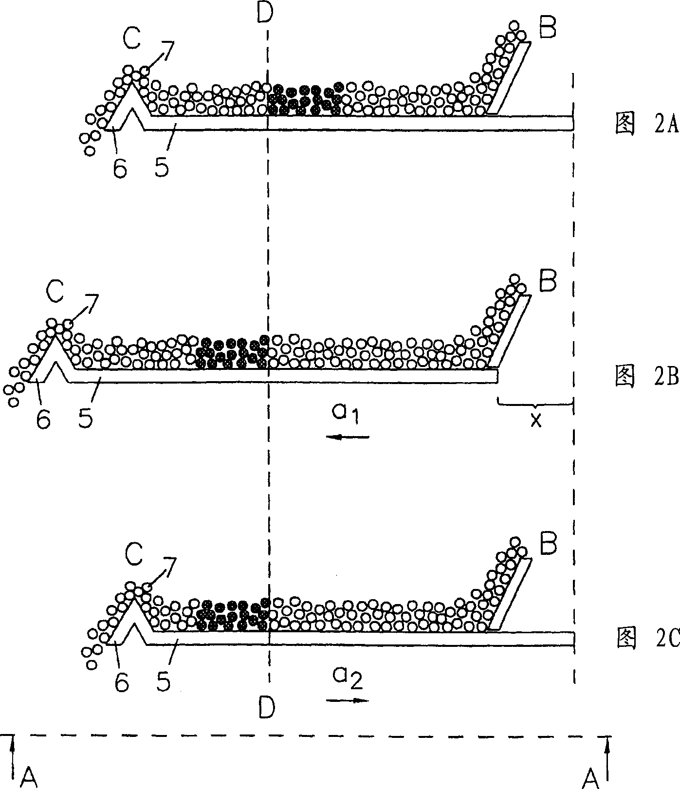
[0030] Material 7, ie food to be cooled, eg crops, corn, cauliflower, crisps, broccoli, etc., is brought into the device in a first position B, see Figs. 2A, 2B, 2C. The material is conveyed above the trough bottom 5 to a second location C where it leaves the trough bottom on a side wall / ...


PUM


Abstract

Apparatus for continuous treatment and transportation of a material (7), consisting of piece goods or granules of solid material, in an at least partly fluidized bed, which apparatus comprises a perforated trough bottom (5) for the material and means (3) for creating an upwardly directed air or gas flow through said trough bottom (5) and said material (7). The trough bottom (5) is disposed to move, from a starting position, in the conveying direction of the material (7) and opposite to the conveying direction of the material, the trough bottom in motion opposite to the conveying direction being disposed, relative to the material (7), to exhibit greater acceleration (a2) than a maximum acceleration (a1) relative to the surroundings in motion in the conveying direction.

Description

technical field [0001] The invention relates to a device for handling and transporting material, including flakes or granules of solid material, in an at least partially fluidized layer, the device comprising a perforated trough bottom for the material and for generating a flow through Means for upward air or air flow of the tank bottom and the material. Background technique [0002] In the hot air treatment of foodstuffs on an industrial scale, continuously operating air treatment units are used which generally work according to the fluidized layer principle. Herein, the term "hot air treatment" refers to cooling or freezing with cold air or gas, and heating, drying or humidification with hot air, gas or airflow or the like. In this case, the air-treated product is conveyed on a continuous process line and enters the fluidized bed at a first location, where it is conveyed to a second location. When the product reaches the second location, it is process...

Claims


Application Information

Patent Timeline
Patent Type & Authority Applications(China)
IPC IPC(8): A23L3/36A23L3/50B01J8/36B01J8/40F25D13/06F26B3/092F26B17/26
CPCA23L3/361B01J8/36F26B3/0923A23L3/50B01J2208/00725F25D13/06B01J8/40F26B17/26
Inventor 鲁宾·拉森
Owner 鲁宾·拉森
Why Eureka
Try Eureka