Drawer-type row-state thermo-sensitive primter

A technology for thermal printers and drawers, which is applied in printing devices, printing, thin material processing, etc., can solve problems such as thermal head exposure, and achieve the effect of improving the direction of operation

Inactive Publication Date: 2002-03-20
SEIKO INSTR INC
View PDF0 Cites 2 Cited by
  • Summary
  • Abstract
  • Description
  • Claims
  • Application Information

AI Technical Summary

Problems solved by technology

[0003] A conventional thermal printer having the above opening / closing structure has a problem in that the thermal head is exposed during operations frequently performed by the user such as loading recording paper or the like.

Method used


Image

  • Drawer-type row-state thermo-sensitive primter
  • Drawer-type row-state thermo-sensitive primter
  • Drawer-type row-state thermo-sensitive primter

Examples


Embodiment Construction

[0015] Preferred embodiments of the present invention will be described in detail below with reference to the accompanying drawings, in which

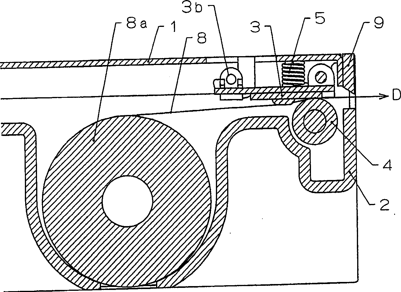
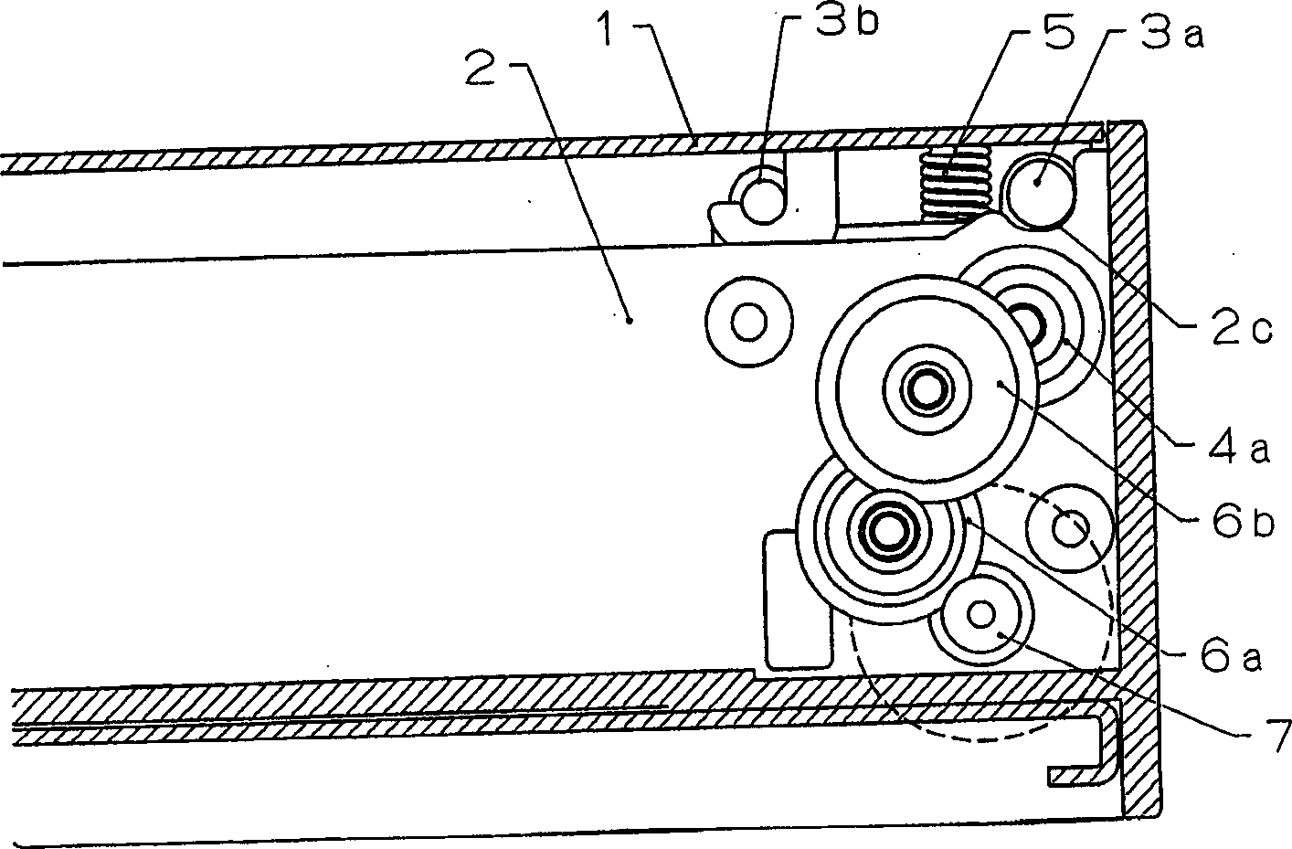
[0016] Figure 1 shows an illustrative side view illustrating an embodiment of the present invention; Figure 1A for the edge figure 2 a cross-sectional side view of line A-A shown; and Figure 1B for the edge figure 2 Cutaway side view of line B-B shown.

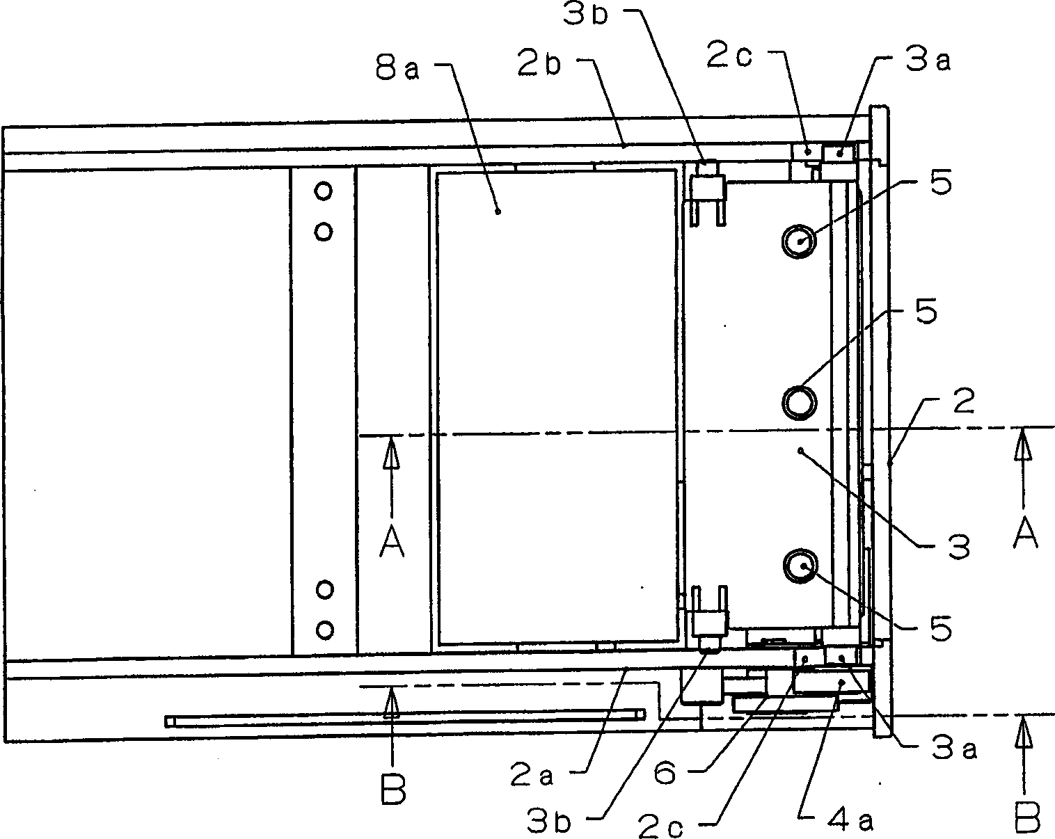
[0017] figure 2 To show a partial perspective top view of the entire device.

[0018] Figures 3 and 4 depict the operation of the various components when opening and closing the second frame 2; Figure 3A and 4A for the edge figure 2 a cross-sectional side view of line A-A shown; and Figure 3B and 4B for the edge figure 2 Cutaway side view of line B-B shown.

[0019] Figure 5 A perspective external view to depict the overall shape of a thermal printer according to the present invention.

[0020] FIG. 6 is a schematic diagram of a conventional clamshell type printer...


PUM


Abstract

In a thermal printer with a drawer-type paper holder, a means is provided, which facilitates the loading of recording paper, reduces the number of parts, and improves the precision in positioning a thermal head and a platen roller, a thermal printer is composed of a first frame 1 by which the thermal head 3 is rotatably supported so that recording paper 8 is brought into pressure contact with a platen roller 4 by a biasing member 5 and a second frame 2 that pivotably supports the platen roller 4, is opened and closed in parallel to the first frame 1, and contains a recording rolled paper 8a. The thermal printer has a configuration in which a first cam 3a provided in the thermal head 3 is guided by a second cam 2c formed in the second frame 2 while being biased by the biasing member 5 and thus the platen roller 4 pivotably supported to the second frame 2 is positioned with respect to the thermal head 3.

Description

technical field [0001] The present invention relates to a printer, and also to a mechanism that separates the platen roller and the thermal head when the recording paper is sandwiched between the print head and the platen roller while the print head and the platen roller are kept in pressure contact . In particular, the present invention relates to a drawer-type thermal printing apparatus (a thermal printer) having improved operability when loading recording paper. Background technique [0002] As a structure in which the platen roller and the thermal head are separated by a considerable distance, an opening / closing structure in which opening and closing are performed by means of the paper holder 10 as shown in FIG. 6 has been adopted. It is operated by the rotary motion, so that the loading of the recording paper can be easily realized. This on / off structure has become widespread, and is characterized in that maintenance operations such as loading recording paper are perf...

Claims


Application Information

Patent Timeline
Patent Type & Authority Applications(China)
IPC IPC(8): B41J11/04B41J11/14B41J15/04B41J29/02B65H16/02B65H20/02
CPCB41J11/14B41J29/026B41J11/04B41J15/042
Inventor 关谷宏彰
Owner SEIKO INSTR INC
Why Eureka
Try Eureka