Parallel reversely dispersed small wave change

A discrete wavelet transform and inverse transform technology, applied in code conversion, instruments, television, etc., can solve the problems of reducing resolution and deformation, and achieve the effect of length reduction

Inactive Publication Date: 2002-04-10
EASTMAN KODAK CO
View PDF1 Cites 2 Cited by
  • Summary
  • Abstract
  • Description
  • Claims
  • Application Information

AI Technical Summary

Problems solved by technology

Each of these subbands is a bandpass filtered and

Method used


Image

  • Parallel reversely dispersed small wave change
  • Parallel reversely dispersed small wave change
  • Parallel reversely dispersed small wave change

Examples


Embodiment Construction

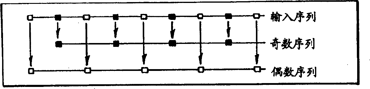
[0020] The present invention includes systems and methods for accelerating the inverse discrete wavelet transform (IDWT) of sub-band data. This is accomplished by partitioning the data input to IDWT operations in a specific and minimally overlapping manner, allowing multiple IDWT operations on these partitions to be implemented in parallel. This partitioning scheme is particularly suitable for IDWT schemes implemented using "lifting" techniques.

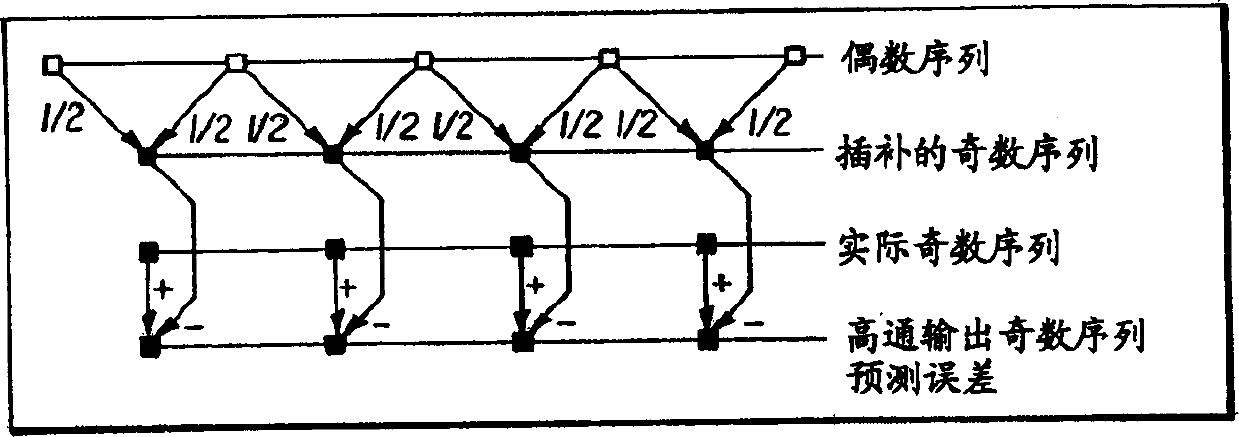
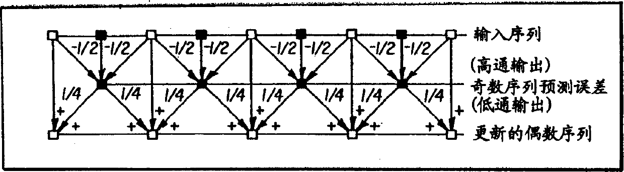
[0021] Lifting is a different approach to designing and implementing wavelet transform filters. For a given filter pair, the resulting transformed data for the lifting implementation is exactly the same as for the regular implementation using convolution.

[0022] Boosting has the following benefits. The memory requirement is reduced by about half, which leads to significant memory savings for multi-dimensional forward and inverse DWTs. Furthermore, boosting simplifies the hardware implementation and image boundaries are easier to...


PUM


Abstract

The object of the present invention to provide a structure and method of processing signals, which includes transforming a signal into subbands by applying a forward discrete wavelet transform (FDWT) to the signal, partitioning the subbands into overlapping subband subsets, inverse transforming the overlapping subband subsets into signal subsets by applying at least one inverse discrete wavelet transform (IDWT) to the overlapping subband subsets, and combining the signal subsets to reproduce the signal. The IDWT is applied to all of the subband subsets in parallel.

Description

field of invention [0001] The present invention relates generally to image compression systems based on wavelets, and more particularly to an image compression system that implements inverse discrete wavelet transform processing in parallel to achieve higher processing speeds. Background technique [0002] Conventional wavelet-based image compression systems employ a two-dimensional forward wavelet transform of an image to transform the image into multiple subbands. Each of these subbands is a bandpass filtered and reduced resolution version of the original image. This allows sub-bands to be amenable to compression by various methods. When reconstructing the original image, it is required that all these sub-bands must first be decompressed, and then use the inverse discrete wavelet transform (IDWT) to transform these sub-bands back to the original image. [0003] While the present invention does not rely on lift (described in more detail below), its utility is greatly enha...

Claims


Application Information

Patent Timeline
IPC IPC(8): H04N7/30G06F17/14G06T9/00H03M7/30
CPCG06F17/148G06T9/007
Inventor J·A·斯马尔M·D·布朗
Owner EASTMAN KODAK CO
Why Eureka
Try Eureka