Illumination system and method for producing light-beam with required form

A lighting system and light beam technology, which is applied in the field of lighting systems, can solve problems such as manufacturing tolerances of fastening devices, limiting system effectiveness and light energy, etc., and achieve the effect of reduced structure size and high efficiency

Inactive Publication Date: 2002-06-19
KONINKLIJKE PHILIPS ELECTRONICS NV
View PDF0 Cites 0 Cited by
  • Summary
  • Abstract
  • Description
  • Claims
  • Application Information

AI Technical Summary

Problems solved by technology

This leads to manufacturing tolerances of the fastening device, wh

Method used


Image

  • Illumination system and method for producing light-beam with required form
  • Illumination system and method for producing light-beam with required form
  • Illumination system and method for producing light-beam with required form

Examples


Example Embodiment

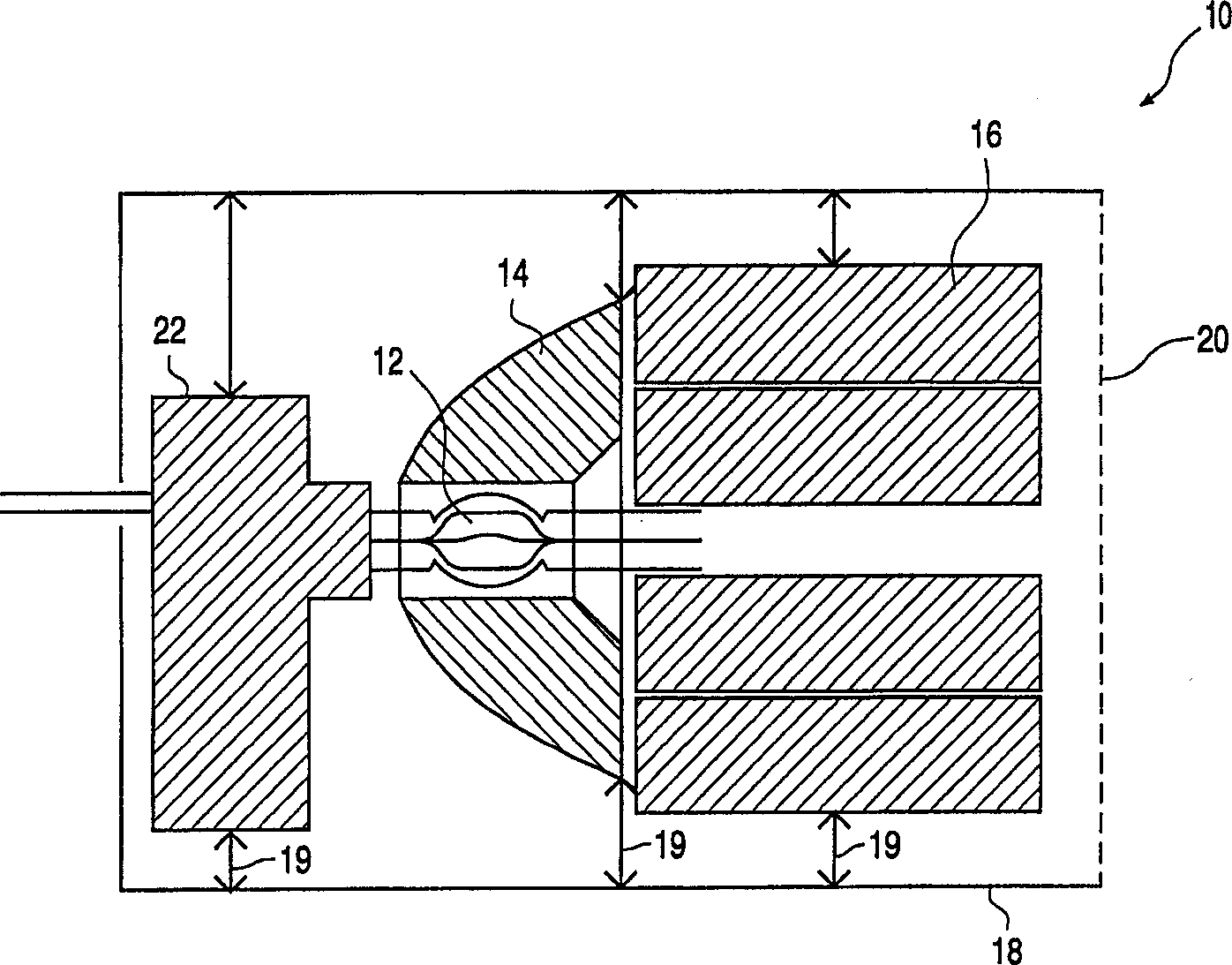
[0029] figure 1 A lighting system is shown, indicated by 10 as a whole. Its main components are a light source 12 in the form of a discharge lamp, a collector 14 and a number of separators 16, which together form a light-collecting separator, arranged with a light transmission Inside the housing 18 of the front part 20. The components for controlling the discharge lamp 12 and a ballast 20 are held in the housing 18 in a suitable and adjustable manner by a corresponding known holding device 24.

[0030] The collector 14 and the separator 16 are solid elements, which means that compared with the usual system, the light guiding and the formation of the beam occur in the transparent material, and the light from the light source to the lighting system is basically not in Moving in the air, but moving in a fixed medium.

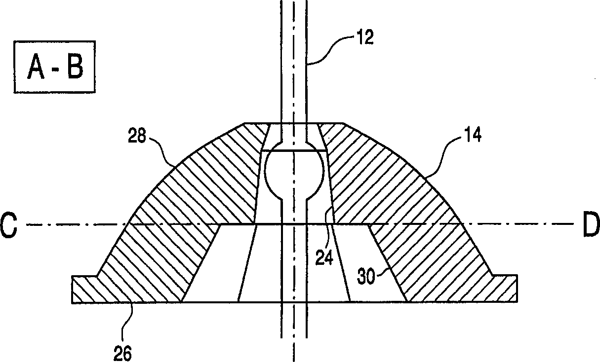
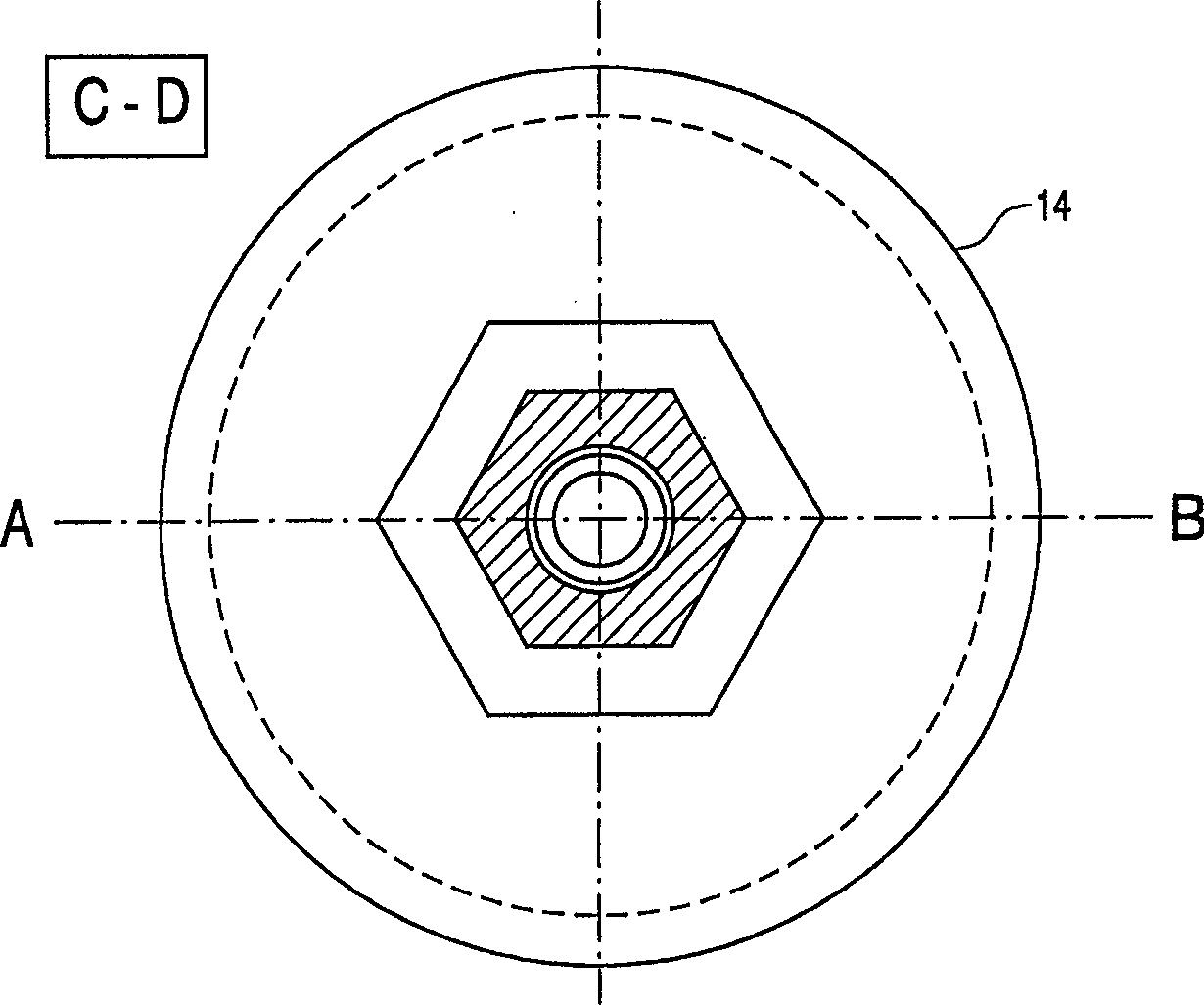
[0031] figure 2 with image 3 Two front views of the collector 14 are shown. One of the main characteristics of the present invention is clearly observed, which co...


PUM


Abstract

In a lighting system for motor vehicles, light from a HID or MPXL lamp is collected by a collector which surrounds the light source at least partly and is guided further to a separator of optical waveguide material, which separator forms a desired light beam via a specially shaped light outlet surface so as to obtain as high as possible a light output.

Description

technical field [0001] The invention relates to a lighting system, in particular for a motor vehicle, and a method for producing a light beam of desired shape. Background technique [0002] Illumination systems and related methods capable of producing light beams of various shapes have been known for a long time. Generally, all related lighting systems and methods use a light source to emit light, which is then formed into a beam by various optical devices, and the desired shape of the beam is obtained. Light sources, especially widely used in the motor vehicle sector, are halogen incandescent lamps, and more recently gas discharge lamps, especially low-pressure gas discharge lamps, such as so-called MPX lamps (Micro Power Xenon Lamps). Such discharge lamps do have advantages over incandescent lamps in terms of service life and energy consumption, but compared to the coils of incandescent lamps, the resulting light arc has no clear demarcations and it is difficult to contro...

Claims


Application Information

Patent Timeline
IPC IPC(8): G02B3/00F21S8/10F21S8/12F21V5/00F21W101/10F21Y101/00
CPCF21S48/1291F21S48/1233F21S48/1186F21S48/1241F21S41/172F21S41/24F21S41/27F21S41/28F21V7/04F21S41/17F21S41/60F21V9/45
Inventor H·蒂斯勒-韦迪
Owner KONINKLIJKE PHILIPS ELECTRONICS NV
Why Eureka
Try Eureka