Front plate unit of split air conditioner

An air conditioner and split-type technology, which is applied to the front panel device field of split-type air conditioners, can solve problems such as unclean appearance of indoor machines, and achieve the effects of beautiful appearance, quick and easy assembly operation, and easy disassembly.

Inactive Publication Date: 2002-07-10
LG ELECTRONICS (TIANJIN) APPLIANCES CO LTD
View PDF0 Cites 14 Cited by
  • Summary
  • Abstract
  • Description
  • Claims
  • Application Information

AI Technical Summary

Problems solved by technology

In this case, there will be a problem that the

Method used


Image

  • Front plate unit of split air conditioner
  • Front plate unit of split air conditioner
  • Front plate unit of split air conditioner

Examples


Example Embodiment

[0036] Implementation

[0037] Below in conjunction with accompanying drawing, the implementation of the present invention is described as follows:

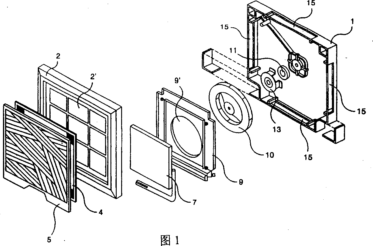
[0038] The description of FIG. 1 has been described in detail in "Background Art", so it is omitted here.

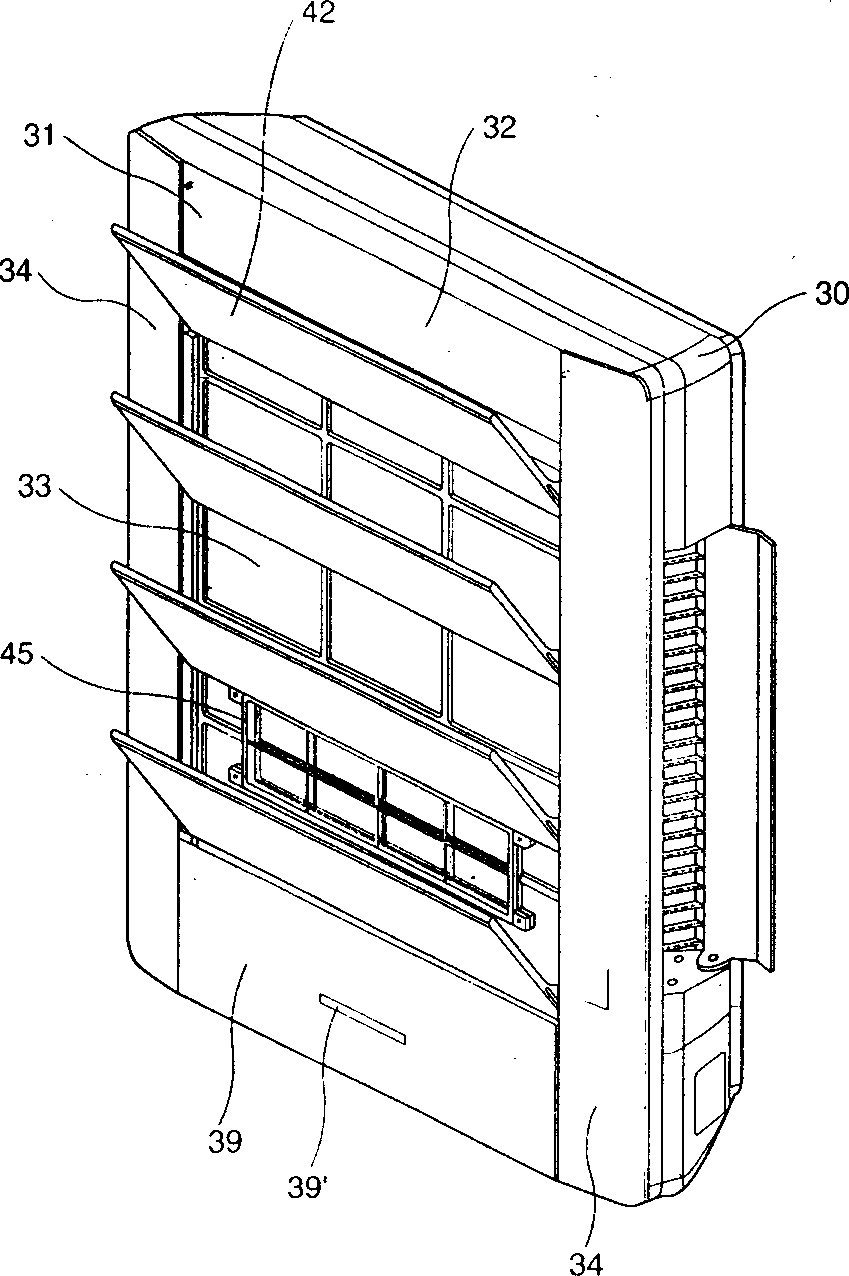
[0039] exist figure 2 , the internal structure of a split-type air conditioner employing a split-type front panel device will now be described.

[0040] The casing (30) forms the appearance. The shape of the shell (30) is a thin hexahedron. A front plate (31) is arranged on the front of the casing (30) to shield the space inside the casing (30).
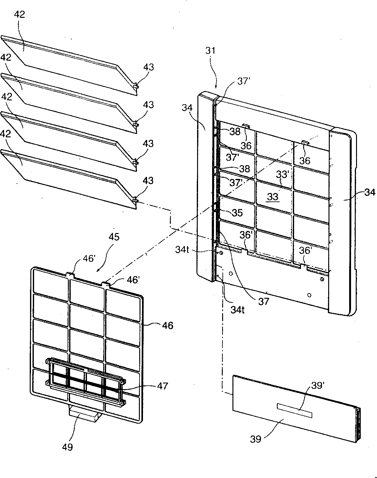
[0041] exist image 3 , the detailed structure of the front plate (31) is shown in the figure. The front panel body (32) is roughly quadrangular, and a quadrangular suction through hole (33) is provided in the center thereof. The suction through-hole portion (33) functions as a channel for sucking the space air that needs to be adjusted int...


PUM


Abstract

The present invention discloses a front plate unit of split air conditioner, and the center part of the front plate has inhaling through hole for holding air purifying filter. There are raised decorative plates at the two ends of the front plant and embedded part installed to the bottom of the grille and between the raised decorative parts. All the surfaces of the grille, the bottom and the decorative plates from one continuous plane. The filter is set inside the space between the front plate and the grille and is one easy-to-assembly and easy-to-disassembly structure.

Description

technical field [0001] The invention belongs to the class of air conditioners, in particular to a front plate device of a split type air conditioner. Background technique [0002] At present, according to the structure of the indoor unit of the split-type air conditioner in the prior art (see Fig. 1), its shell (1) forms the appearance of the indoor unit. Shell (1) shape is very thin rectangle, and the length of up, down, left, and right directions is longer than the front and rear dimensions. A front plate (2) is arranged on the front of the casing (1). [0003] Such a front plate (2) is provided with a suction through-hole portion (2') for sucking air that needs to be adjusted in the space. A filter (4) is provided at the suction through hole portion (2') in order to purify the air passing through the place. A filter (4) is installed in the suction through hole portion (2'). A suction grille (5) is arranged at the suction through hole ...

Claims


Application Information

Patent Timeline
IPC IPC(8): F24F13/00
Inventor 姜声玟
Owner LG ELECTRONICS (TIANJIN) APPLIANCES CO LTD
Why Eureka
Try Eureka