Lens barrel with variable dioptric strength and camera

A technology of lens barrel and focus, which is applied to cameras, focusing devices, instruments, etc., and can solve the problems of inconvenient hand-holding of the lens barrel

Inactive Publication Date: 2002-09-18
CANON KK
View PDF2 Cites 4 Cited by
  • Summary
  • Abstract
  • Description
  • Claims
  • Application Information

AI Technical Summary

Problems solved by technology

Furthermore, if the lens group sticks out too much, it becomes inconvenient to hold the lens barrel

Method used


Image

  • Lens barrel with variable dioptric strength and camera
  • Lens barrel with variable dioptric strength and camera
  • Lens barrel with variable dioptric strength and camera

Examples


Embodiment Construction

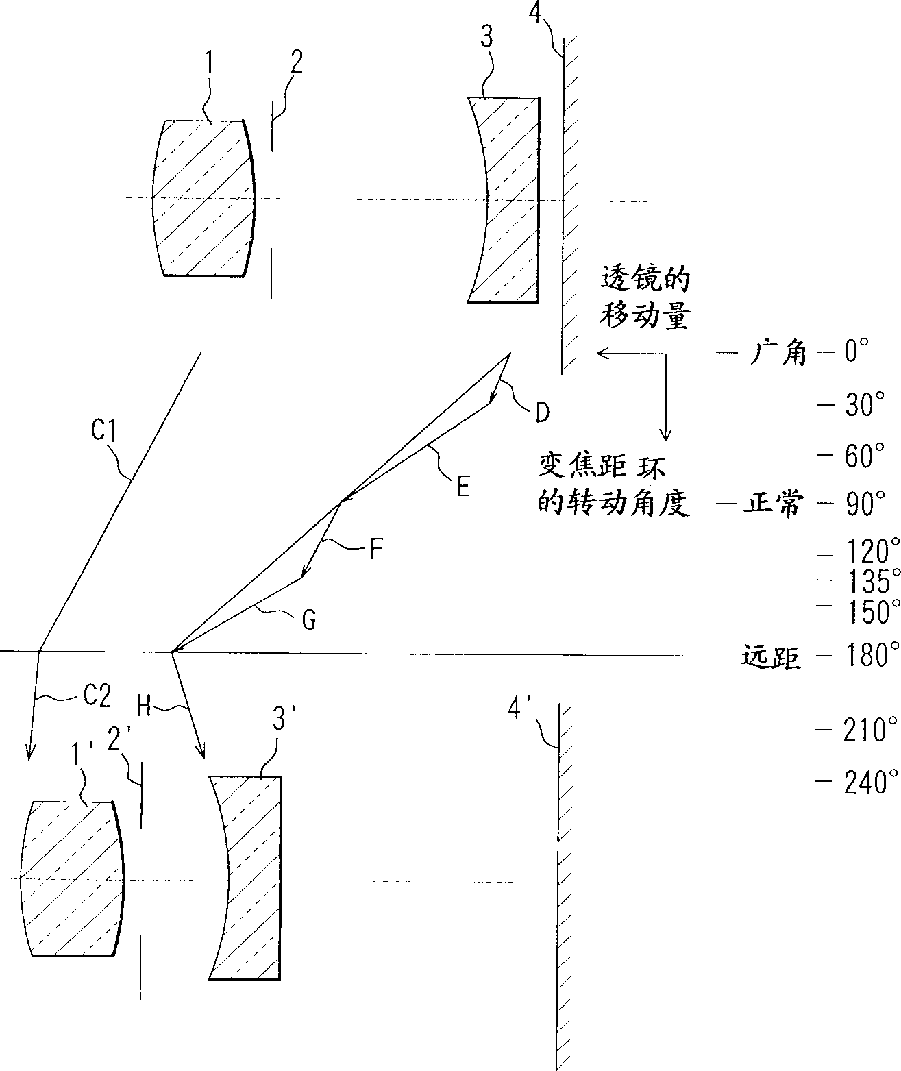
[0045] figure 1 is a schematic diagram showing the relationship between the rotation angle of the zoom lens (not shown in the figure) and the movement amount of the photographic lens in the direction of the optical axis. Here, figure number 1 denotes a positive lens unit, 2 denotes a diaphragm, which is also a shutter blade, 3 denotes a negative lens, and 4 denotes an image plane.

[0046] Arrows C1 and C2 indicate the amount of movement of the positive lens unit 1 relative to the rotation angle of the zoom ring in the direction of the optical axis. In addition, arrows D to H indicate the amount of movement of the negative lens unit 3 relative to the rotation angle of the zoom ring in the direction of the optical axis.

[0047] When the zoom ring is at the rotation angle of 0°, the positive lens unit 1, the shutter blade 2 and the negative lens unit 3 are in such a relationship as figure 1 The diagram in the middle panel is shown relative to image plane 4 . At this time, ...


PUM


Abstract

The invention discloses a variable-focus lens barrel and camera, the lens barrel has a first lens unit located on the side closest to the object, and a cam barrel with first cams, and the first cams alternately and continuously have a a set of variable-focus cam sections that drive the first lens unit to change its power in the direction of the optical axis, and a set of focus cam sections that drive the first lens unit driven by the corresponding variable-focus cam sections , so as to focus in the direction of the optical axis, and the focus cam portion of the first cam that drives the first lens unit is raised less in the direction of the optical axis at the telephoto end than the focus cam that drives the first cam of the first lens unit The amount of lift of the part in the direction of the optical axis at other variable focus positions.

Description

technical field [0001] The present invention relates to a lens barrel, and more particularly, the present invention relates to a lens barrel which moves a lens group and stops them at a series of positions of the zoom ring by a rotational operation of a zoom ring on an optical axis, And at the same time, it can be adjusted from infinity to close distance. The lens barrel according to the present invention is suitable for cameras and digital cameras with 35mm wide film. Background technique [0002] Japanese Patent No. Hei 6-100707 proposes a device for variable magnification and Japanese Unexamined Patent No. Hei 9-80291 proposes a device for changing the position of the zoom ring, which may be achieved by rotation of a separate zoom ring Operation to change focal power and focus adjustment. [0003] Figure 13 and Figure 14 It is a main part diagram of a variable magnification device proposed in Japanese Patent No. Hei 6-100707. They show the relationship between the r...

Claims


Application Information

Patent Timeline
Patent Type & Authority Applications(China)
IPC IPC(8): G02B7/04G02B7/10
CPCG02B7/10
Inventor 增田晋一
Owner CANON KK
Why Eureka
Try Eureka