High-frequency filter

A high-frequency filter and frequency characteristic technology, applied in waveguide-type devices, impedance networks, electrical components, etc., can solve the problems of reducing the size of electrodes, limiting the miniaturization of filters, etc., to prevent damage and damage, and increase the adjustment range. Effect

Inactive Publication Date: 2002-10-02
PANASONIC CORP
View PDF0 Cites 3 Cited by
  • Summary
  • Abstract
  • Description
  • Claims
  • Application Information

AI Technical Summary

Problems solved by technology

Therefore, the electrode size cannot be reduced while maintaining high precision in the existing process, which limits the miniaturization of the filter

Method used


Image

  • High-frequency filter
  • High-frequency filter
  • High-frequency filter

Examples


Embodiment 1

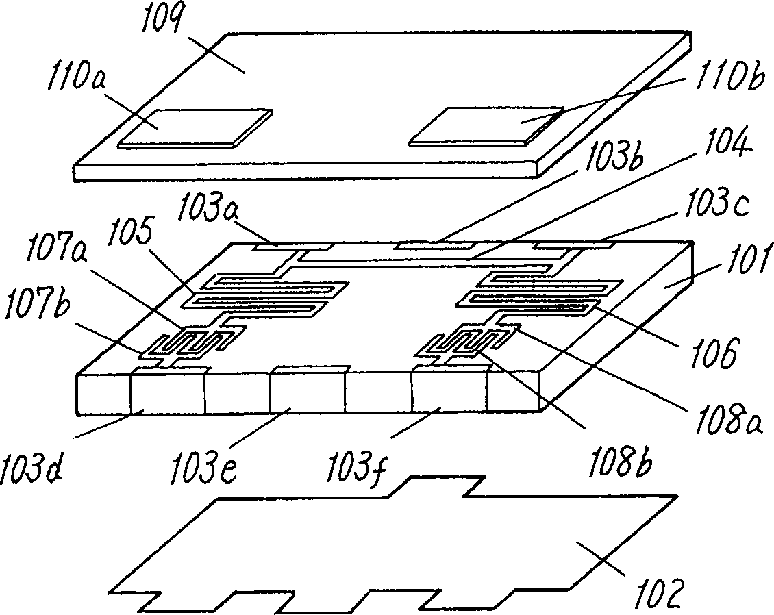
[0038] figure 1 It is a diagram showing the configuration of the high-frequency filter according to Embodiment 1 of the present invention. In the high-frequency filter of this embodiment, the ground electrode 102 is formed on the lower surface of the dielectric 101, and the end surface electrodes 103a, 103b, 103c, 103d, 103e, and 103f are formed from the side surfaces of the dielectric 101 and partially curved upward. Also, on the upper surface of the dielectric 101, the first transmission line electrode 104, the second transmission line electrode 105, the third transmission line electrode 106, the first comb-shaped electrodes 107a / 107b, and the second comb-shaped electrodes 108a / 108b are formed. Furthermore, a dielectric layer 109 is laminated on the upper side of these electrodes, and adjustment dielectric layers 110a and 110b are formed on the upper side to at least partially overlap the first comb-shaped electrodes 107a / 107b and the second comb-shaped electrodes 108a / 108b...

Embodiment 2

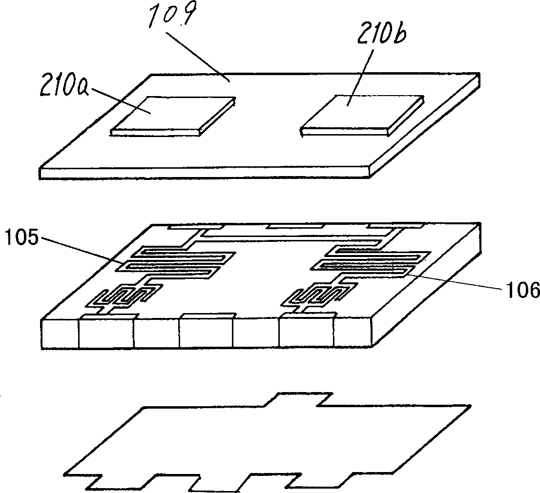
[0043] figure 2It is a diagram showing the configuration of a high-frequency filter according to Embodiment 2 of the present invention. The difference between the high-frequency filter of this embodiment and the first embodiment lies in the formation position of the dielectric layer for adjustment. In this embodiment, the adjustment dielectric layers 210a and 210b, such as figure 2 As shown, the dielectric layer 109 overlaps at least a portion of the transmission line electrodes 105 and 106 . In this way, by changing the effective permittivity of these transmission line electrodes and adjusting the inductance value of the inductor, the frequency characteristics of the high-frequency filter can be adjusted.

[0044] In addition, in the high-frequency filter of this embodiment, a magnetic medium layer for adjustment may be used instead of a dielectric layer for adjustment. In this way, the range of adjustable inductance values ​​can be increased. In addition, in the high-f...

Embodiment 3

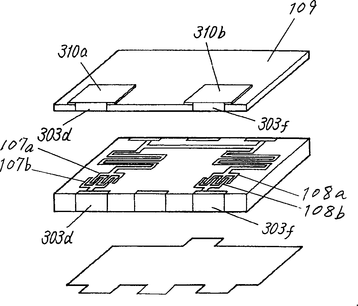
[0046] image 3 It is a diagram showing the configuration of a high-frequency filter according to Embodiment 3 of the present invention. The high frequency filter of this embodiment, such as image 3 As shown, the conductor layers 310a and 310b for adjustment are provided, instead of the dielectric layer for adjustment, and end surface electrodes 303d and 303f are used for grounding. The structure is the same as that of the first embodiment except that. exist image 3 Among them, the conductive layers 310a and 310b for adjustment are formed on the comb-shaped electrodes, since a capacitance proportional to the occupied area of ​​the comb-shaped electrodes is added, so the range of adjustable capacitance can be enlarged.


PUM


Abstract

The present invention provides a high-frequency filter used in mobile communication equipment such as a mobile phone, which has an inductance component, a capacitance component, and a resistance component formed by a conductor pattern. This filter has a conductor pattern formed on the surface of the dielectric layer and an adjustment layer for adjusting filter frequency characteristics formed to cover at least a part of the conductor pattern. Also, in this high-frequency filter, the filter frequency characteristics are adjusted after the conductor pattern is formed and fired. Therefore, in this high-frequency filter, the manufacturing yield can be improved. Further, the conductor pattern can use extremely thin lines, and the capacitor can use comb-shaped electrodes, so that the electrode layer can be a single layer. Therefore, miniaturization and thinning can be achieved by gravure printing technology or thin film forming technology.

Description

technical field [0001] The present invention relates to a high-frequency filter mainly used in mobile communication devices such as portable telephones. Background technique [0002] In recent years, the demand for mobile communications such as mobile phones has been increasing, so the bandwidth of the used frequency bands has become insufficient, and there is a tendency to shift to higher frequency bands. Therefore, mobile communication devices such as mobile phones are also required to be able to adapt to higher frequency bands. In short, the high-frequency filters used therein are required to reduce the bandwidth, and the circuit elements constituting the filters are also required to have higher dimensional accuracy. [0003] Existing high-frequency filters generally have Figure 5 composition shown. which is, [0004] (1) The first ground electrode 502 is formed on the upper surface of the first dielectric layer 501 , and the second dielectric layer 503 is laminated o...

Claims


Application Information

Patent Timeline
Patent Type & Authority Applications(China)
IPC IPC(8): H01P1/203H01P1/205H03H7/06H03H7/075
CPCH03H7/06H03H2001/0085
Inventor 栉谷洋胜又雅昭水野雅之
Owner PANASONIC CORP
Why Eureka
Try Eureka