
IGBT module

A branch circuit and magnetic ring technology, applied in the field of electronic components, can solve the problems of low system efficiency, large size, high power consumption, etc.

Inactive Publication Date: 2021-07-30
常州易控汽车电子股份有限公司
View PDF0 Cites 0 Cited by
  • Summary
  • Abstract
  • Description
  • Claims
  • Application Information

AI Technical Summary

Problems solved by technology

[0005] At present, a single IGBT module often cannot meet the system requirements in terms of output power, and directly using a module with a high current level will also greatly increase the cost. In this way, a method of parallel connection current expansion is proposed, but there is a problem of current sharing in parallel connection. If the problem is not solved properly, the system will be unstable
[0006] At present, most of the current sharing methods are to connect resistors and inductors in series in the main circuit, which can prevent the IGBT with fast switching speed from overloading, and effectively suppress the problem of uneven peak current, but there are problems of excessive power consumption and large volume.
[0007] The methods in the prior art all have their own problems: in the parallel resistance method of the main circuit, since the current of the main circuit is very large, if the current sharing resistor is connected in series in the main circuit, even if the resistance value is small, it will bring greater power. consumption, resulting in low system efficiency
[0008] In the main circuit series inductance method, due to the large current of the main circuit, the overcurrent capacity of the required inductance will be large, resulting in large volume and power consumption.
[0009] There is an urgent need for an IGBT module that can not only meet the requirements of high power output, but also overcome the problem of current sharing

Method used


Image

  • IGBT module

Examples


Embodiment Construction

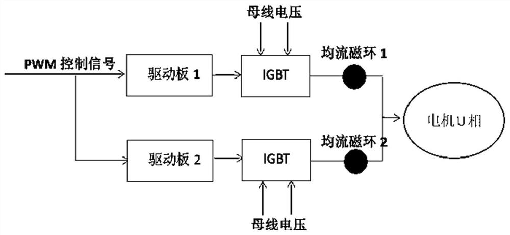
[0029] The technical solutions of the present invention will be further described below in conjunction with the accompanying drawings and through specific implementation methods.

[0030] The present invention mainly adopts the method of current sharing inductance to improve the dynamic current sharing effect of the parallel IGBT, and the current sharing inductance adopts the method of sleeve magnetic ring design, this scheme realizes the soft switching of the IGBT parallel current sharing circuit, reduces the switching process Power loss, prevent IGBT overheating, and effectively protect IGBT devices and circuits.

[0031] like figure 1 As shown, it is the circuit diagram of the IGBT module of the present invention, the first branch is composed of the first IGBT driver board and the first IGBT device in series; the lower two branches are composed of the second IGBT driver board and the second IGBT device in series; the IGBT module of the present invention consists of The fir...


PUM


Abstract

The invention provides an IGBT module, and belongs to the technical field of electronic components. In the prior art, when an IGBT module solves the current sharing problem, power consumption is large, and the size of a device is large. The IGBT module provided by the invention comprises a first branch circuit and a second branch circuit; the first branch comprises a first IGBT driving board and a first IGBT module series connection structure. The second branch comprises a second IGBT driving board and a second IGBT module series connection structure. The input end of the IGBT module receives a PWM control signal; the output end of the IGBT module, namely the output end of the first branch and the output end of the second branch, is connected with the input end of a motor, and is sleeved with a nanocrystalline magnetic ring; the current sharing problem is solved, the power consumption is low, and the device size is small.

Description

technical field [0001] The invention relates to the technical field of electronic components, in particular to an IGBT module. Background technique [0002] The IGBT module is a modular semiconductor product that is packaged by IGBT (insulated gate bipolar transistor chip) and FWD (freewheeling diode chip) through a specific circuit bridge; the packaged IGBT module is directly applied to inverters, UPS uninterrupted power supply and other equipment. [0003] The IGBT module has the characteristics of energy saving, convenient installation and maintenance, and stable heat dissipation; most of the products currently sold on the market are such modular products, and the so-called IGBT also refers to the IGBT module; There will be more and more in the market. [0004] IGBT is the core device of energy conversion and transmission, commonly known as the "CPU" of power electronic devices. As a national strategic emerging industry, it is widely used in rail transit, smart grid, ae...

Claims


Application Information

Patent Timeline
Patent Type & Authority Applications(China)
IPC IPC(8): H02M1/088H02P27/08
CPCH02M1/088H02P27/08
Inventor 姜泽军孙富荣廖绍文李中方成郝守刚
Owner 常州易控汽车电子股份有限公司
Learn More