Resilient member with deformed element and method of forming same

A technology of elastic components and parts, applied in the field of equipment containing elastic materials, can solve problems such as no pressure fit, abnormally large rotational resistance torque, violent impact, etc., and achieve the effect of small fit tolerance, low cost, and good bearing performance

Inactive Publication Date: 2002-10-09
LORD CORP
View PDF0 Cites 9 Cited by
  • Summary
  • Abstract
  • Description
  • Claims
  • Application Information

AI Technical Summary

Problems solved by technology

[0003] A particular problem with prior art rod end constructions is that it is desirable that the inner liner 5 be pressed into the plastic sleeve 3 with very little pressure so that the parts 3, 5 are united before assembly
Therefore, in some cases, the pressure between the liner 5 and the sleeve 3 is so great that it causes an abnormally large rotational resistance torque between them
In extreme cases, the plastic sleeve 3 can break
Conversely, in the case of certain error accumulations, there will be very little or no pressure fit between the parts, causing the inner liner 5 to fall out of the sleeve 3
What's more, when the fit is very loose, it will cause abnormal deflection between the connecting parts, resulting in violent impact during use

Method used


Image

  • Resilient member with deformed element and method of forming same
  • Resilient member with deformed element and method of forming same
  • Resilient member with deformed element and method of forming same

Examples


Embodiment Construction

[0031] Detailed description of preferred embodiments

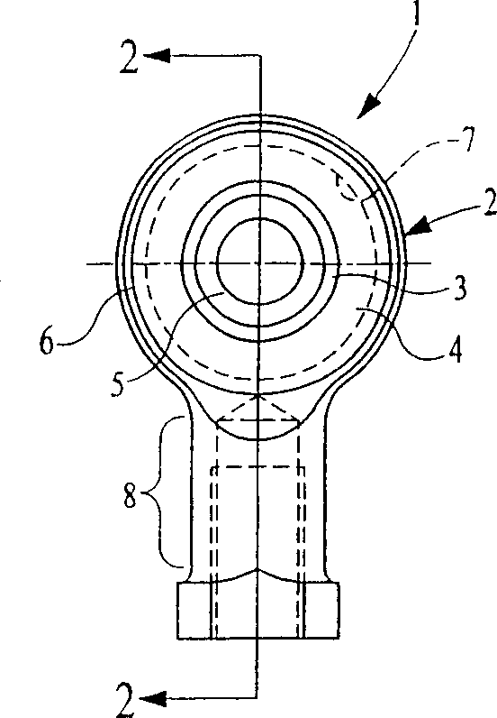
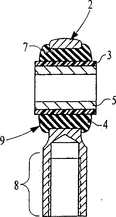
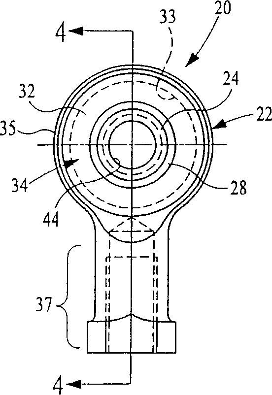
[0032] The first embodiment of the present invention Figure 3-4 Shown. The present invention is illustrated with an embodiment of an elastic rod end, but it can be seen from the following description that the present invention can be widely used in bearings, shock absorbers, brackets and shock absorbers. The invention can be used to permanently fix one part relative to another part when needed. Moreover, when a good bearing function is required, the present invention provides an effective and low-cost method of approximate line-line fit between parts.

[0033] According to the present invention, the elastic member 20 in the rod end structure includes a rigid first part 24, such as an inner sleeve, a deformable second part 28, such as a thermoplastic cylindrical sleeve as shown, and a Two-part elastic part 32, such as synthetic rubber or other rubber-like elastic material parts. The third part 22, such as the rigid rod end cas...


PUM


Abstract

An elastic component and a forming method thereof, the elastic component is used for isolating vibration and/or sound transmission. The elastic member (20) includes a first part (24) having a suitable profile (26), a second part (28) made of deformable material (such as thermoplastic material), and elastic part (32) (such as rubber). During the molding process, the second part (28) is deformed so that its shape and size are consistent with the surface (25) of the first part (24). In a preferred embodiment, the second part (28) is plastically deformed and conforms to the contour (26) of the first part (24), thereby creating a mechanical interlock. This article introduces the rotation and translation interlocking of the component and the method of forming this interlocking.

Description

Technical field [0001] The invention relates to the field of equipment containing elastic materials, such as elastic bearings, frames, shock absorbers, rod end structures, and the like. More particularly, the present invention relates to an improved elastic member that provides isolation of vibration transmission or smooth movement. Background of the invention [0002] Elastic rod end structures, that is, rod end structures containing elastic joints, are widely used in various connections, and are usually used with chains and cables. This typical rod end structure is shown in Figures 1 and 2, including a rigid outer sleeve 2, a plastic sleeve 3, elastic parts 4 and a rigid metal inner sleeve 5. The jacket 2 includes a main body part 6 which contains a transverse window 7 and a threaded part 8 extending radially from the main body part. The elastic part 4 is bonded to the outer surface of the inner sleeve 5 after being hardened. It includes a joint joint 9 which is slidably placed...

Claims


Application Information

Patent Timeline
Patent Type & Authority Applications(China)
IPC IPC(8): F16C11/04F16C27/06F16F1/38
CPCF16C27/063F16F1/3842F16F2226/00F16C11/083
Inventor 保罗·J·巴尔克赞杰勒德·M·奥里克
Owner LORD CORP
Why Eureka
Try Eureka