Uninterupted hydraulic source for liquid-holding deep sea hydraulic system

A technology of hydraulic system and hydraulic source, applied in the direction of fluid pressure actuating device, accumulator device, etc., which can solve problems such as failure to work normally and impact

Inactive Publication Date: 2002-10-23
ZHEJIANG UNIV
View PDF0 Cites 3 Cited by
  • Summary
  • Abstract
  • Description
  • Claims
  • Application Information

AI Technical Summary

Problems solved by technology

Therefore, the traditional hydraulic system stores energy through a single accumulator, and the method used in an emergency state is seriously affected by the uncertainty of the water depth of the hydraulic source, and it is almost impossible to work normally.

Method used


Image

  • Uninterupted hydraulic source for liquid-holding deep sea hydraulic system
  • Uninterupted hydraulic source for liquid-holding deep sea hydraulic system

Examples


Embodiment Construction

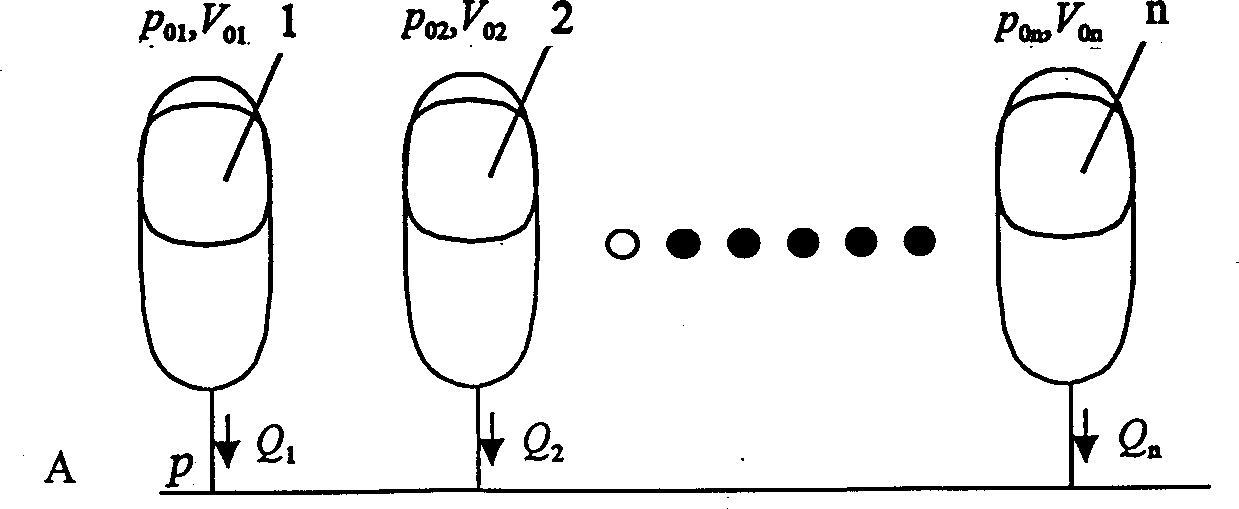
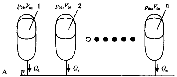
[0009] As shown in the figure, it includes 1~n accumulators with different pre-charging pressures, which are connected in parallel and connected to the hydraulic source A.

[0010] n is 2×(maximum deep sea water pressure / oil source output pressure difference) + 1 ultra-high pressure accumulator, the volume is selected to be more than 2.5 times of the maximum release flow, and the pre-charging pressure is controlled separately. The first one is 1 / 2 oil source The accumulators whose output pressure difference is 1 / 2 of the output pressure difference of the oil source are connected in parallel and connected to the hydraulic source A.

[0011] In the figure, p represents the output pressure of the hydraulic source, and its absolute value is equal to the output pressure difference of the hydraulic source plus the sum of the external water pressure;

[0012] p 01 ~p 0n Indicates the pre-charge pressure of each accumulator, V 01 ~V 0n Indicates the volume of each accumulator, Q ...


PUM


Abstract

The present invention discloses a uninterrupted hydraulic source of liquid volume type deep-sea underwater hydraulic system, which is characterized by that it comprises 1-n energy-storing devices with different precharged pressures which are parallel-connected on the hydraulic source. When the depth of water in which the hydraulic source is positioned in shallower, the energy-storing device with higher precharged pressure doen not work, and the energy-storing device with lower precharged pressure is being in optimum working zone and can release more flow, and when the depth of water in which the hydraulic source is placed is deeper, the energy-storing device with high precharged pressure is being in optimum working zone and can release more flow, so that the proper precharged pressure combination only is selected.

Description

technical field [0001] The present invention relates to boosters or liquid pressure converters. Background technique [0002] The deep sea underwater hydraulic system generally adopts an adaptive oil tank that automatically balances the oil return pressure and the external water pressure, and the absolute value of its output pressure is equal to the sum of the output pressure difference of the hydraulic source plus the external water pressure. Therefore, the traditional hydraulic system uses a single accumulator to store energy, and the method used in emergency conditions is seriously affected by the uncertainty of the water depth of the hydraulic source, and it is almost impossible to work normally. [0003] in water deep 1500 2000 2500 3000 3500 4000 4500 5000 5500 6000 6500 7000 releasable flow 1.5 1 ...

Claims


Application Information

Patent Timeline
Patent Type & Authority Applications(China)
IPC IPC(8): F15B1/00
Inventor 顾临怡陈鹰邱敏秀杨灿军朱亮叶瑛
Owner ZHEJIANG UNIV
Why Eureka
Try Eureka