Hydrodynamic three-stage cavitation device

A fluid power and pipe body technology, applied in the field of fluid power three-stage cavitation device, can solve the problems of secondary pollution, high energy consumption, low efficiency, etc., and achieve the effect of improving efficiency, improving cavitation efficiency, and reducing energy consumption

Inactive Publication Date: 2020-12-08
HARBIN UNIV OF SCI & TECH
View PDF9 Cites 2 Cited by
  • Summary
  • Abstract
  • Description
  • Claims
  • Application Information

AI Technical Summary

Problems solved by technology

In terms of sewage treatment, traditional treatment methods generally have high energy consumption, low efficiency, and secondary pollution. Hydrodynamic cavitation technology is a new type of physical and chemical water treatment technology. The collapse of cavitation bubbles in hydraulic cavitation leads to micro jets and shock waves. The generation of high temperature and high pressure environment is formed, so as to effectively degrade organic pollutants

Method used


Image

  • Hydrodynamic three-stage cavitation device
  • Hydrodynamic three-stage cavitation device
  • Hydrodynamic three-stage cavitation device

Examples


Embodiment Construction

[0019] The specific structure and implementation mode of the present invention will be further described below in conjunction with the accompanying drawings.

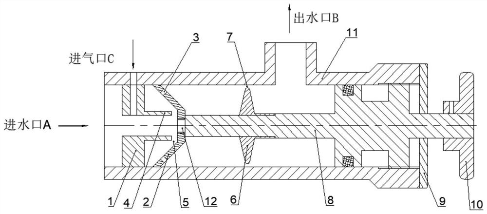
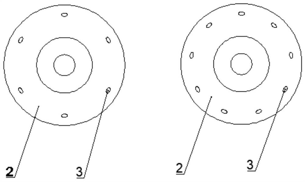
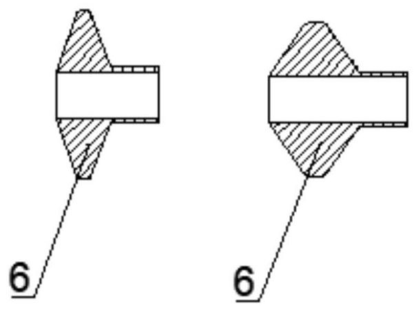
[0020] Such as Figures 1 to 3 , a hydrodynamic three-stage cavitation device, including an orifice plate 1, a frustum-shaped orifice plate 2, a baffle element 6, a long rod 8, an end cap 9, a handle 10, and a cavitation pipe body 11. The orifice plate 1 is installed at a designated position near the water inlet A, and the gas can pass through the orifice plate 1 and enter the fluid through the air inlet hole C, and the orifice plate 1 and the cavitation pipe 11 are fixed by screw connection or other connection methods. The orifice plate 1 and the cylinder 4 are integrally structured, and the gap between the cylinder 4 and the frustum-shaped orifice plate 2 forms the first annular hole 5; the bottom surface opening 12 of the frustum-shaped orifice plate 2 is screwed to the long rod 8 or fixed by other connection methods...


PUM


Abstract

A hydrodynamic three-stage cavitation device belongs to the field of fluid cavitation and comprises a water inlet A, a water outlet B, an air inlet C, a pore plate 1, a circular-truncated-cone-shapedpore plate 2, circular truncated cone-shaped pore plate holes 3, a cylinder 4, a first annular hole 5, a baffle element 6, a second annular hole 7, a long rod 8, an end cover 9, a handle 10, a cavitation pipe body 11 and a circular truncated cone-shaped pore plate bottom hole 12. The device is characterized in that the distribution of the circular holes 3 and the shape of the axial section of thebaffle element 6 can be changed, the circular-truncated-cone-shaped pore plate 2 and the baffle element 6 are matched with the long rod 8 and can coaxially move along with the long rod 8, and then thepositions and the strength of the three cavitation fields are changed; the pore plate 1 is provided with an air inlet, and a large number of microbubbles are mixed in water inlet fluid; and enough gas nuclei are provided for three cavitation fields at the downstream. A three-stage cavitation structure is adopted, so that the defect of insufficient cavitation is overcome, and more energy is released; The cavitation device is simple in structure, convenient to operate and low in cost, the cavitation efficiency is effectively improved, and the cavitation device has very considerable developmentand application prospects.

Description

[0001] Technical field [0002] The invention discloses a fluid power three-stage cavitation device, which belongs to the field of fluid power cavitation. Background technique [0003] With the continuous development of science and technology, due to the instantaneous accumulation of high energy and high turbulence in hydraulic cavitation, it can provide a very special high-pressure and high-temperature environment for physical and chemical reactions that are difficult to achieve under normal conditions, making cavitation technology widely used in Chemical, pharmaceutical, refining, sewage treatment and many other fields. In terms of sewage treatment, traditional treatment methods generally have high energy consumption, low efficiency, and secondary pollution. Hydrodynamic cavitation technology is a new type of physical and chemical water treatment technology. The collapse of cavitation bubbles in hydraulic cavitation leads to micro jets and shock waves. The generation of org...

Claims


Application Information

Patent Timeline
Patent Type & Authority Applications(China)
IPC IPC(8): C02F1/34B01F3/04C02F101/30
CPCC02F1/34C02F2101/30B01F23/20
Inventor 韩桂华赵志伟侯进军
Owner HARBIN UNIV OF SCI & TECH
Why Eureka
Try Eureka