Alternative rotary pump

A technology of alternating rotation and pump body, applied in the direction of rotary piston pump, rotary piston machine, pump, etc., can solve the problems of difficult to increase pumping pressure, short service life, complex structure, etc., and achieve strong self-priming ability, high Pressure, high efficiency

Inactive Publication Date: 2002-11-06
蔡康人
View PDF0 Cites 5 Cited by
  • Summary
  • Abstract
  • Description
  • Claims
  • Application Information

AI Technical Summary

Problems solved by technology

However, the structure of this kind of rotary pump is relatively complicated, the sealing requirements are high, the wear is relatively large, the service life is short, and the pumping pressure is difficult to increase.

Method used


Image

  • Alternative rotary pump
  • Alternative rotary pump
  • Alternative rotary pump

Examples


Embodiment Construction

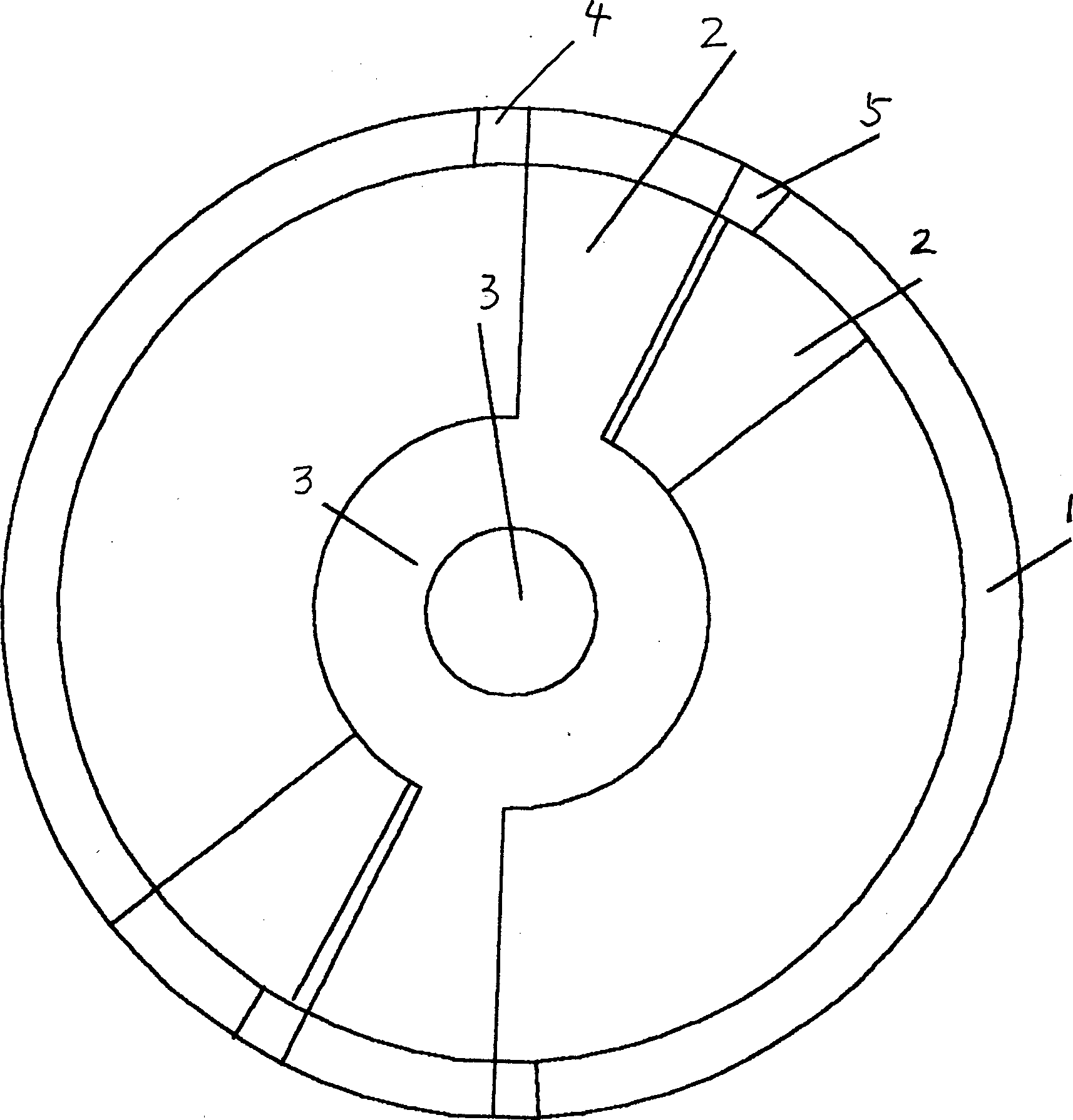
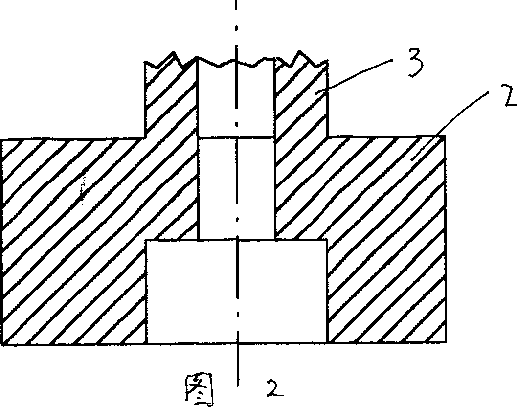
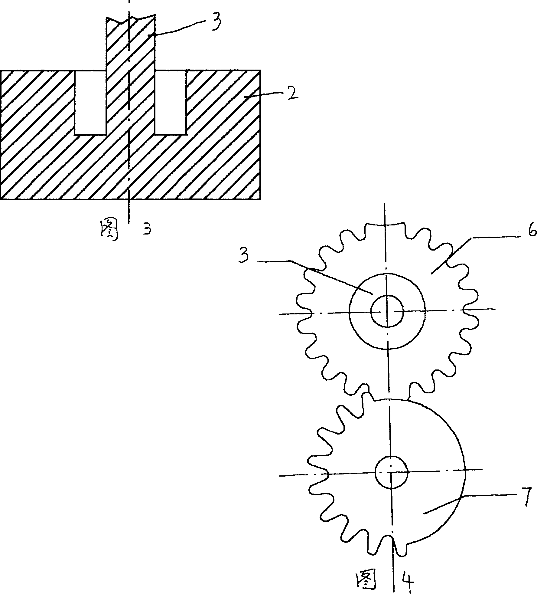
[0011] The present invention will be described in detail below in conjunction with the accompanying drawings: the present invention mainly includes a pump body 1, a pump blade 2 in the pump body, and a driving mechanism connected to the pump blade 2, etc. FIG. The pump body 1 is provided with two rotary vanes 2 which are nested with each other through their respective intermediate rotary vane shafts 3 . The respective two ends of the two rotary vanes 2 are close to the inner wall of the pump and can move relative to each other. The two rotary vanes 2 are placed adjacent to each other and are at the initial position. A suction port 4 and a discharge port 5 are symmetrically opened on the top. A driven gear 6 is respectively fixed on the two rotating blade shafts 3, and a driving gear 7 connected to the driving mechanism meshes with the driven gear 6, and the driven gear 6 and the driving gear 7 constitute a group of incomplete gear transmission mechanisms, That is, the driven ...


PUM


Abstract

The alternative rotary pump includes mainly pump body and driving mechanism connected to pump blade, the pump blade consists of at least two rotary sheets cascaded via the shaft, the the driving mechanism is connected via separate gear units to the rotary sheet shaft. The present invention has high efficiency, high pressure, no effluence of the pressure variation to flow rate, constant flow rate and powerful spontaneous imbibitions capacity.

Description

technical field [0001] The invention relates to a displacement rotary pump, which belongs to the category of pumps. Background technique [0002] In the prior art, the structure of the positive displacement rotary pump includes a pump body, a rotating pump blade in the pump body and a driving mechanism connected with the pump blade, wherein the rotating pump blade is mainly an eccentric wheel, and the wheel wall surface of the eccentric wheel and the pump The rolling on the surface of the body, through the inlet and outlet valves, realizes the continuous change of the inner volume of the pump body, and achieves the purpose of pumping. However, the structure of this kind of rotary pump is relatively complicated, the sealing requirements are high, the wear is relatively large, the service life is short, and the pumping pressure is difficult to increase. Contents of the invention [0003] The purpose of the present invention is to overco...

Claims


Application Information

Patent Timeline
Patent Type & Authority Applications(China)
IPC IPC(8): F04C2/077
Inventor 蔡康人
Owner 蔡康人
Why Eureka
Try Eureka