Multiflow overcold condenser

A multi-flow, condenser technology, used in subcoolers, evaporators/condensers, refrigerators, etc., to solve problems such as size constraints

Inactive Publication Date: 2002-11-20
SANDEN CORP
View PDF8 Cites 19 Cited by
  • Summary
  • Abstract
  • Description
  • Claims
  • Application Information

AI Technical Summary

Problems solved by technology

The disadvantage of this traditional structure is that the condenser and the liquid tank are separated from each other, and their size is limited due to the limitation of the volume occupied by the refrigeration circuit in the vehicle
However, even in these structures, since the liquid tank presses the entire heat exchange core, it is still a space problem that needs to be solved

Method used


Image

  • Multiflow overcold condenser
  • Multiflow overcold condenser
  • Multiflow overcold condenser

Examples


Embodiment Construction

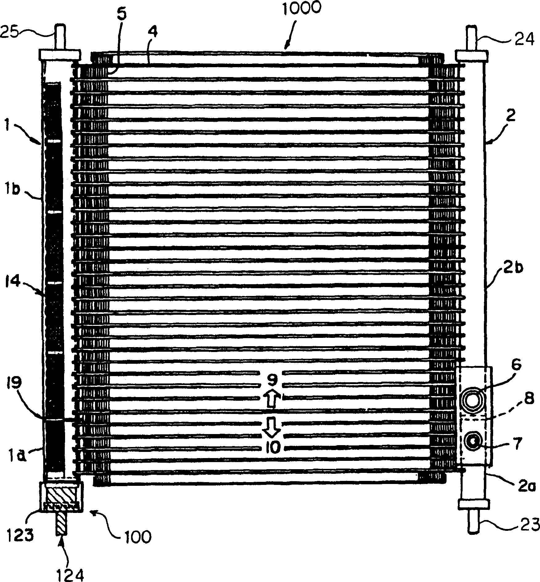
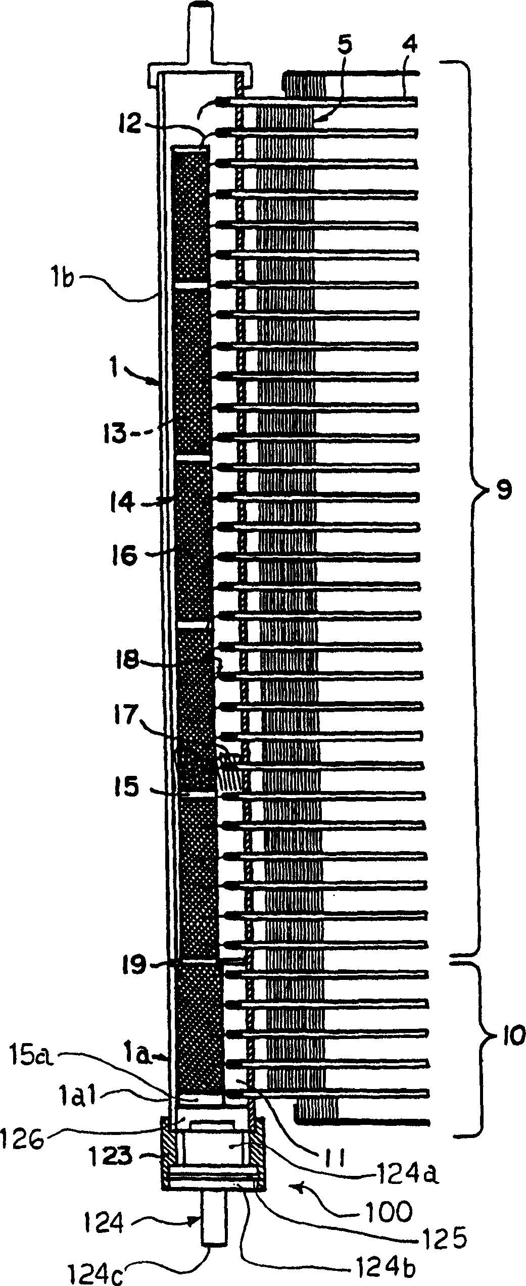
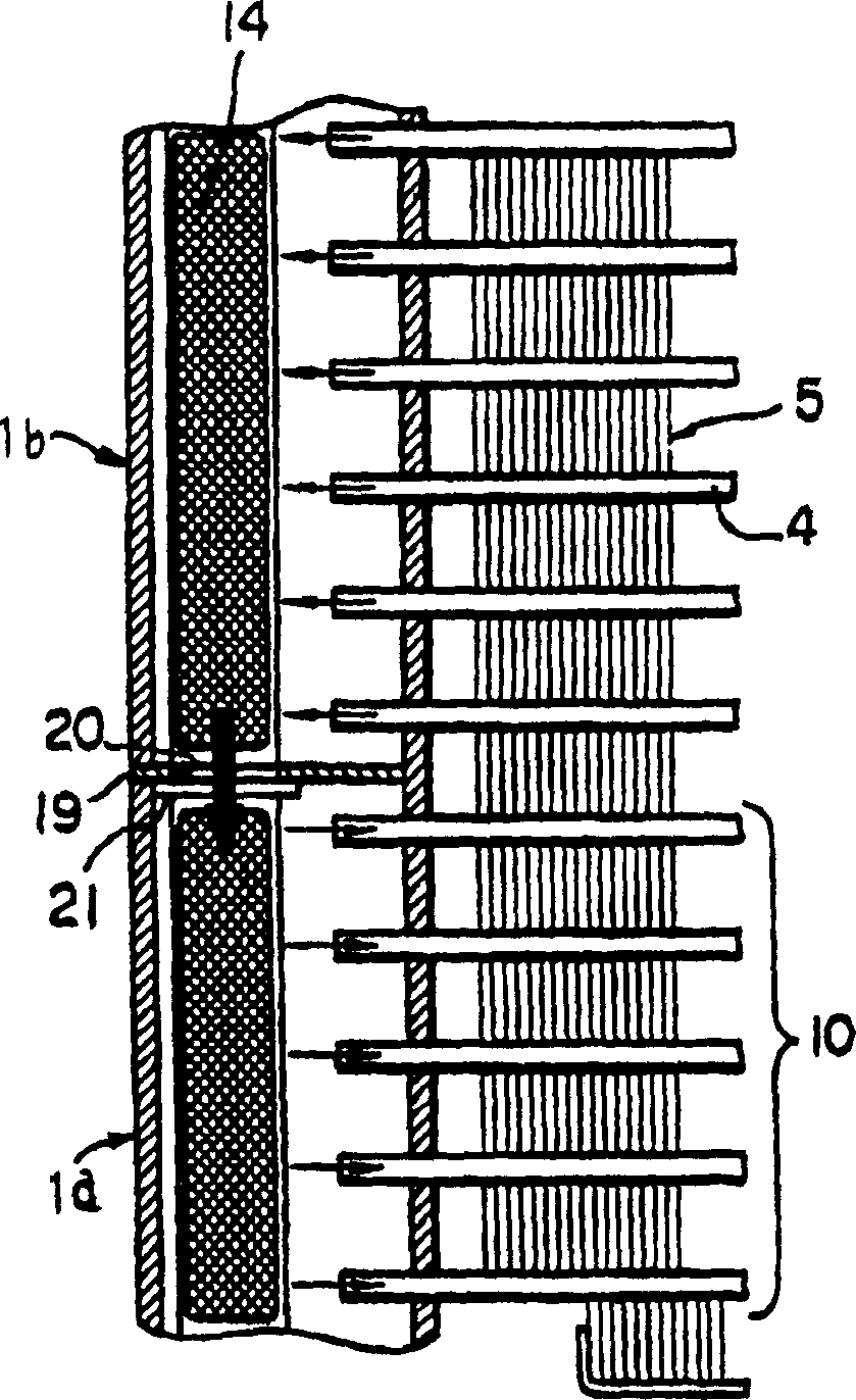
[0067] figure 1 Shown is a multi-flow type sub cool condenser (multi-flow type sub cool condenser) according to the first embodiment of the present invention. Hereinafter, the multi-flow subcooling condenser is referred to as condenser for short. The condenser 1000 mainly includes a first header 1, a second header 2, a plurality of flat heat transfer tubes 4 and a plurality of corrugated fins 5. The first header 1 and the second header 2 are connected to each other through a plurality of heat transfer tubes 4. A plurality of heat transfer tubes 4 and a plurality of corrugated fins 5 are alternately stacked. The first header 1 is divided into an upper pipe portion 1b and a lower pipe portion 1a by a partition 19. The second header 2 is divided into an upper tube portion 2b and a lower tube portion 2a by a partition 8. The inlet pipe 6 is connected to the second header 2 near the upper portion of the partition 8. The refrigerant flows into the upper pipe portion 2b of the second h...


PUM


Abstract

A multi-flow subcooling condenser, comprising: a pair of headers, a plurality of flat heat transfer tubes connecting the pair of headers, and corrugated fins arranged alternately with the heat transfer tubes. The condenser includes a refrigerant condensing core section and a subcooling cooling core section. The lower part of one of the headers of the condenser, which serves as a liquid tank to collect liquid refrigerant for delivery to the subcooled cooling core section, also has a desiccant. A plug mechanism is provided to the end of the desiccant including the manifold, in the plug mechanism the plug can be arbitrarily fixed or removed, whereby the desiccant can be replaced.

Description

Technical field [0001] The invention relates to a multi-flow subcooling condenser used for a condenser in a vehicle air-conditioning device. Specifically, the present invention relates to a multi-flow subcooled condenser whose header contains a desiccant. Background technique [0002] Multi-flow subcooling condensers are usually used in vehicle air conditioners. Specifically, the so-called supercooling condenser usually has a heat exchange part called a supercooling part, which further cools the liquefied refrigerant. The liquefied refrigerant must be collected in a certain place before flowing into the subcooling part. The container that collects the liquefied refrigerant before it is supercooled is called a liquid tank. In Japanese Patent Laid-open Publications No. 10-122705, No. 9-170854, and No. 9-170853, the liquid tank is arranged near the header of the condenser. The disadvantage of this traditional structure is that the condenser and the liquid tank are separated from eac...

Claims


Application Information

Patent Timeline
Patent Type & Authority Applications(China)
IPC IPC(8): F25B39/04F25B40/02F25B43/00
CPCF25B39/04F25B40/02F25B43/003F25B2339/0441F25B2400/162F25B2500/01F28F2220/00
Inventor 门浩隆和田贤一上岛博光新村利治渡濑大翼冈田茂
Owner SANDEN CORP
Why Eureka
Try Eureka