One-way overrunning clutch

A one-way overrunning and clutch technology, applied to one-way clutches, clutches, mechanical equipment, etc.

Inactive Publication Date: 2002-11-20
TOK BEARING CO LTD
View PDF0 Cites 17 Cited by
  • Summary
  • Abstract
  • Description
  • Claims
  • Application Information

AI Technical Summary

Problems solved by technology

[0025] Furthermore, when the above-mentioned plastic or metal-ceramic bearing pads need to change the torque corresponding to the use of the one-way overrunning clutch, a new metal mold for manufacturing the bearing pads must be made.

Method used


Image

  • One-way overrunning clutch
  • One-way overrunning clutch
  • One-way overrunning clutch

Examples


Embodiment

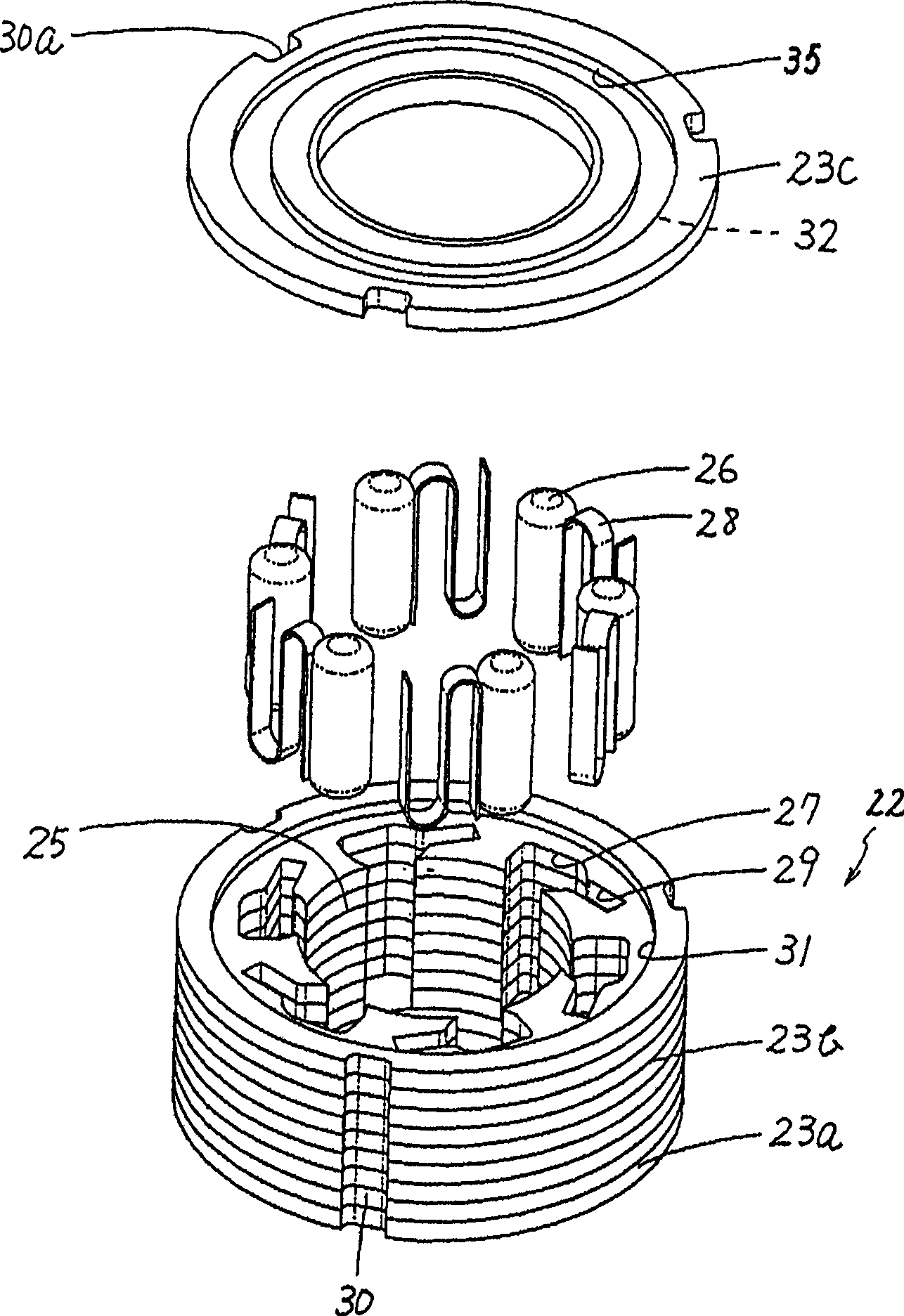
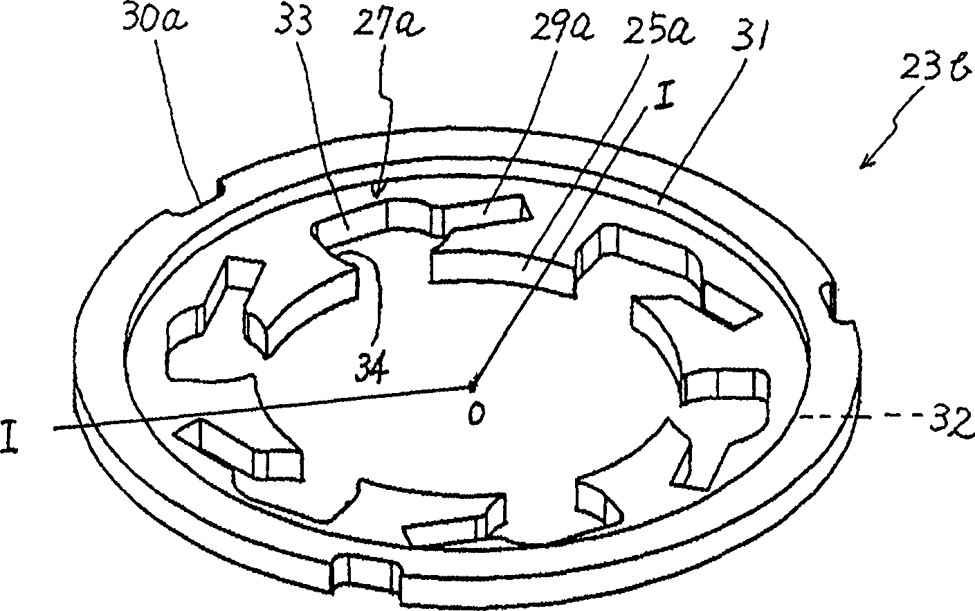
[0051] figure 1 ~5 shows embodiment 1 of the present invention. The most important feature of the present invention is that the metal plate member is stamped by press processing, and the stamped plate member is laminated to form the bearing bush 22 of the one-way overrunning clutch, and a press-fit part is formed around the entire circumference of the bearing bush 22. The structure other than these features is the same as the conventional case, so its detailed description will be omitted.

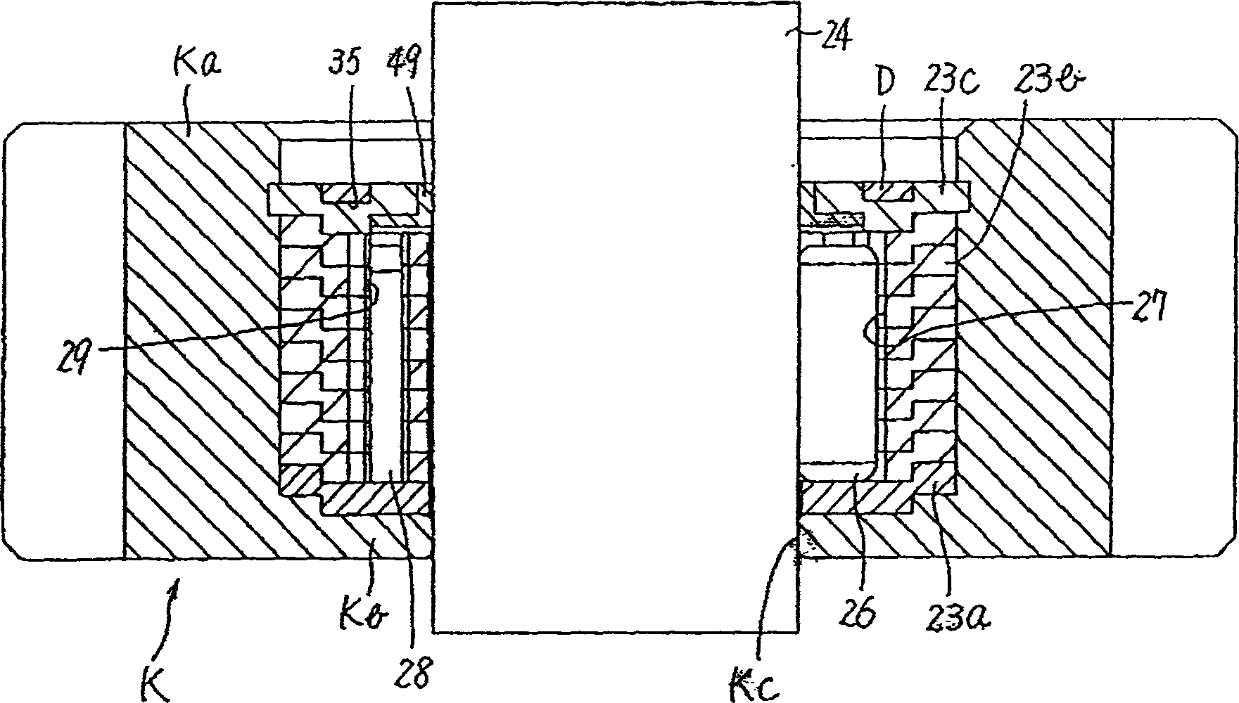
[0052] figure 1 Shown is an overall view of the bearing bush 22 of Embodiment 1, figure 2 It is a cross-sectional view when the bearing bush 22 is installed in the outer ring K and the rotating shaft 24 is inserted into the bearing bush 22 . the above figure 2 The shown outer wheel K is designed as a gear part, and the outer wheel K can also be designed and utilized as a pulley component or other components in addition to the above-mentioned gear components. As above figure 1 , ...


PUM


Abstract

The object of the present invention is to provide a one-way overrunning clutch with high strength, adjustable torque, convenient manufacture and assembly, and miniaturization. This one-way overrunning clutch is provided with a bearing bush supporting the rotating shaft and a clutch mechanism arranged in the bearing bush. When the rotating shaft inserted into the bearing bush rotates in one direction of the clutch mechanism, the rotating shaft rotates and slides in the bearing bush. When it rotates in one direction, its rotation and sliding are locked. The above-mentioned bearing bush is formed by laminating a plurality of plate members, and the press-fit recess formed on one surface of the above-mentioned plate member around the entire circumference is press-fitted into the recess formed on the adjacent plate member. Press-fit protrusions on the other side.

Description

technical field [0001] The invention relates to a one-way overrunning clutch. When the rotating shaft rotates in one direction, the rotating shaft rotates and slides in the bearing bush, and when it rotates in the other direction, it forms an integral body with the bearing bush to rotate. Background technique [0002] Figure 10 Shown is a general configuration diagram of a conventional one-way overrunning clutch. Figure 11 This is a cross-sectional view of a conventional one-way overrunning clutch. Such as Figure 10 , 11 Shown, this one-way overrunning clutch is made up of outer wheel 1, the bearing bush 2 that packs into outer wheel 1 inboard, the bearing cover 3 of outer wheel 1. [0003] The outer ring 1 is composed of a cylindrical portion 5 and a closing portion 6 that closes one end of the cylindrical portion 5 . A plurality of convex portions 7 are formed inside the cylindrical portion 5 , and a bearing hole 8 for supporting the rotary shaft 4 is provided in the...

Claims


Application Information

Patent Timeline
Patent Type & Authority Applications(China)
IPC IPC(8): F16D41/066
CPCF16D41/066
Inventor 榎本勇生本多修欣並木真平
Owner TOK BEARING CO LTD
Why Eureka
Try Eureka