Suction and exhaust device

An exhaust device and air technology, which is applied in the direction of pipeline layout, shielding with air flow, and household stoves/stoves, etc., can solve the problems of difficulty in dispersing the air flow pressure, disordered blowing flow, and inability to generate a rotating flow with flow velocity distribution. Uniform flow velocity distribution to achieve the effect of exhaust

Inactive Publication Date: 2002-12-11
DAIKIN IND LTD
View PDF0 Cites 30 Cited by
  • Summary
  • Abstract
  • Description
  • Claims
  • Application Information

AI Technical Summary

Problems solved by technology

[0018] That is, in Figure 13 In the structure of the air supply and exhaust device shown, since the outside air is introduced into the wider blowing air rotation space in the above-mentioned outside air blowing chamber 4 through an air supply pipe 5, the dynamic pressure of the introduced air flow is difficult to disperse. , there is a difference in achieving uniform rectification effect on all the rectification surfaces of the above-mentioned rectification plate 6. The part with high dynamic pressure passes through the rectification plate 6 early, while the part with low dynamic pressure passes through slowly.
Therefore, a swirling flow with a uniform flow velocity distribution cannot be generated, and part of the blown flow is chaotic, making it difficult to form a reliable air curtain flow.
[0019] Different from the above-mentioned problems, in general air supply and exhaust devices, the swirling flow generating guide vanes 30a, 30a, ... cannot swirl and blow out the air from the above-mentioned air blowing port 3 to form an air curtain flow, and this problem becomes more significant. question

Method used


Image

  • Suction and exhaust device
  • Suction and exhaust device
  • Suction and exhaust device

Examples


Embodiment 1

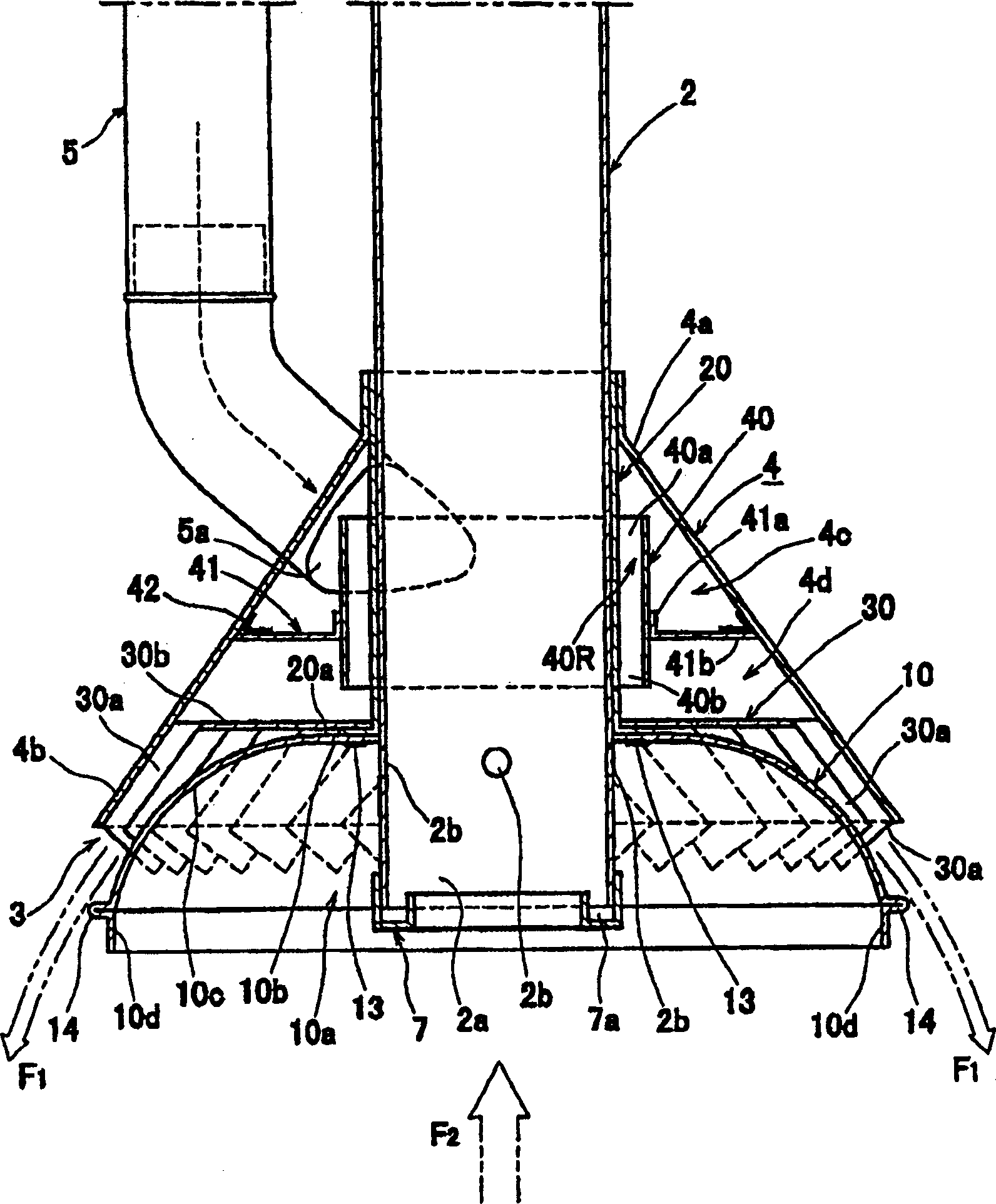
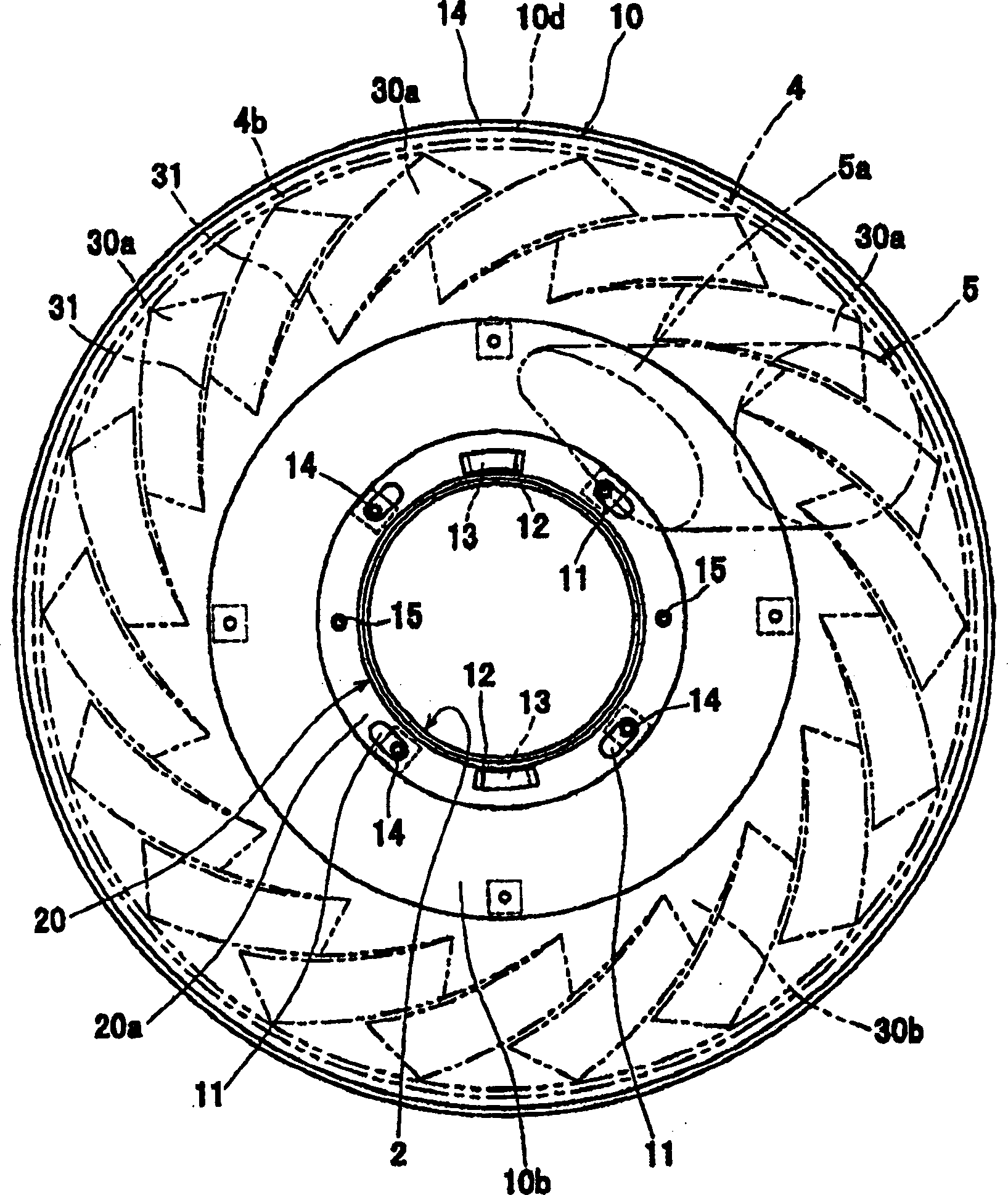
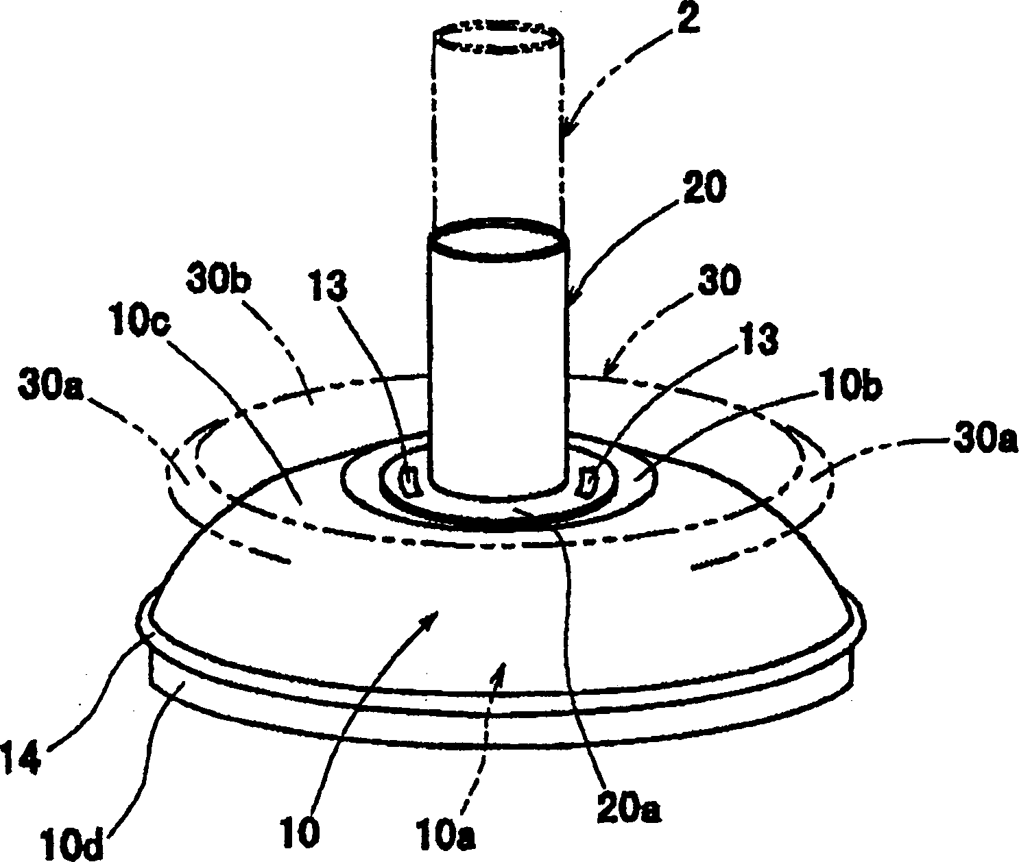
[0056] Figure 1 to Figure 8 Shown is the structure of the cyclone type local ventilation device formed by the air supply and exhaust device according to Embodiment 1 of the present invention.

[0057] The cyclone-type local ventilation device is installed on the upper part of the heating tableware in a predetermined local area such as a gas stove in a general household kitchen or a business kitchen of a restaurant, etc. F1 encloses the heating tableware in an air curtain shape, and the spiral swirling vortex F1 utilizes the external air introduced from the outside to pass through the inner center of the spiral swirling vortex F1 acting on the air curtain and toward the suction direction. The suction negative pressure makes the tornado-shaped suction swirling vortex F2 generated upward in the air-curtain-shaped spiral swirling vortex F1, and the tornado-shaped rising swirling vortex F2 can efficiently attract the gas from the above-mentioned predetermined local area. Exhaust ...

Embodiment 2

[0081] under Figure 9 and Figure 10 The structure of the cyclone type local ventilation device constituted by the air supply and exhaust device according to the second embodiment of the present invention is shown.

[0082] In the structure of the cyclone-type local ventilator of the above-mentioned Embodiment 1, in this embodiment, the upper end side opening (inflow port) 40a side and the lower end side opening (outflow port) 40b side of the flow rectification passage 40 are provided respectively. The straightening plates 43, 44 having a plurality of small holes 43a, 43a, . . . , 44a, 44a, . These rectifying plates 43, 44 adopt a structure such as a punched plate.

[0083] In this way, if rectification plates 43, 44 are respectively provided on the upper end side opening (inflow port) 40a side and the lower end side opening (outflow port) 40b side of the rectification passage 40R that completes the above-mentioned rectification action, in the inflow rectification passage 4...

Embodiment 3

[0090] under Figure 11 and Figure 12 Shown is the structure of the cyclone type local ventilation device constituted by the air supply and exhaust device according to Embodiment 3 of the present invention.

[0091] In the structure of the cyclone-type local ventilator in the above-mentioned embodiment 1, in this embodiment, the rectification passage 50R is provided on the outer peripheral side of the rectification passage 40R to form two sets of rectification passages that are curved in the vertical direction, continuous, and arranged side by side in the radial direction. The channel is characterized by further improving the rectification effect.

[0092] That is, in this structure, by leaving a predetermined interval on the outer peripheral side of the first cylindrical wall 40 forming the rectifying passage 40R of the first embodiment, and further providing the large-diameter second cylindrical wall 50 forming the second rectifying passage 50R, And leave the second cylin...


PUM


Abstract

An air supply and exhaust device, which uses the air blowing outlet 3 on the lower side of the circumferential opening to introduce the air above the predetermined air supply space from the air supply pipe 5 with a predetermined air supply pressure as an air curtain flow outside the predetermined local area. Blow out, and suck the air in the above-mentioned predetermined local area surrounded by the air curtain flow through the air suction port 2a inside the air blowing port 3, and discharge it to the upper part of the air suction pipe 2, and the air suction pipe 2 runs through the air blowing direction The central part of the reverse air supply space extends to the outside. The above-mentioned air blowing space is divided by the partition plate 41 into upper and lower first air blowing spaces 4c where the air from the air blowing pipe 5 is introduced and a second air blowing space 4d that expands in the direction of the air blowing port 3. The first and second air blowing spaces 4c, 4d are communicated with each other through annular rectifying passages 40R, 50R with small passage diameters extending vertically around the outer periphery of the suction pipe 2 . Therefore, the velocity distribution of the airflow blown out from the air outlet is made uniform, and a stable air curtain flow can be formed.

Description

technical field [0001] The present invention relates to an air supply and exhaust device that forms an air curtain flow (air curtain) surrounding the outer periphery of a predetermined local area, and sucks air in the local area in the air curtain flow against it to exhaust air. Background technique [0002] For example, as a ventilation device for ventilating a predetermined local area, on the one hand, it sends air curtain-like air around the outer periphery of the local area, and on the other hand, it sucks the air in the above-mentioned local area in the air curtain flow and discharges it. . The inventors of the present invention will file an application for the above-mentioned ventilator. [0003] For example, Figure 13 One example is shown. [0004] exist Figure 13 Among them, firstly, the symbol 4 is a generally conical external air supply chamber arranged on the upper part of the above-mentioned local area, and a predetermined interval is left below the inner sid...

Claims


Application Information

Patent Timeline
Patent Type & Authority Applications(China)
IPC IPC(8): F24F7/06F24F7/08F24F9/00F24F13/06
CPCF24F7/06F24F7/08F24F9/00F24F2013/0616F24C15/2028F24F2221/46F24F13/06
Inventor 菊池芳正成川嘉则
Owner DAIKIN IND LTD
Why Eureka
Try Eureka