Tube fitting with indicating means

A technology for pipe joints and joint bodies, which is applied in the field of pipe joints and can solve problems such as the uselessness of checking and reinstalling joints

Inactive Publication Date: 2003-01-08
SWAGELOK CO
View PDF2 Cites 23 Cited by
  • Summary
  • Abstract
  • Description
  • Claims
  • Application Information

AI Technical Summary

Problems solved by technology

Since the manual gauges discussed above require a fixed axial dimension, it is

Method used


Image

  • Tube fitting with indicating means
  • Tube fitting with indicating means
  • Tube fitting with indicating means

Examples


Embodiment Construction

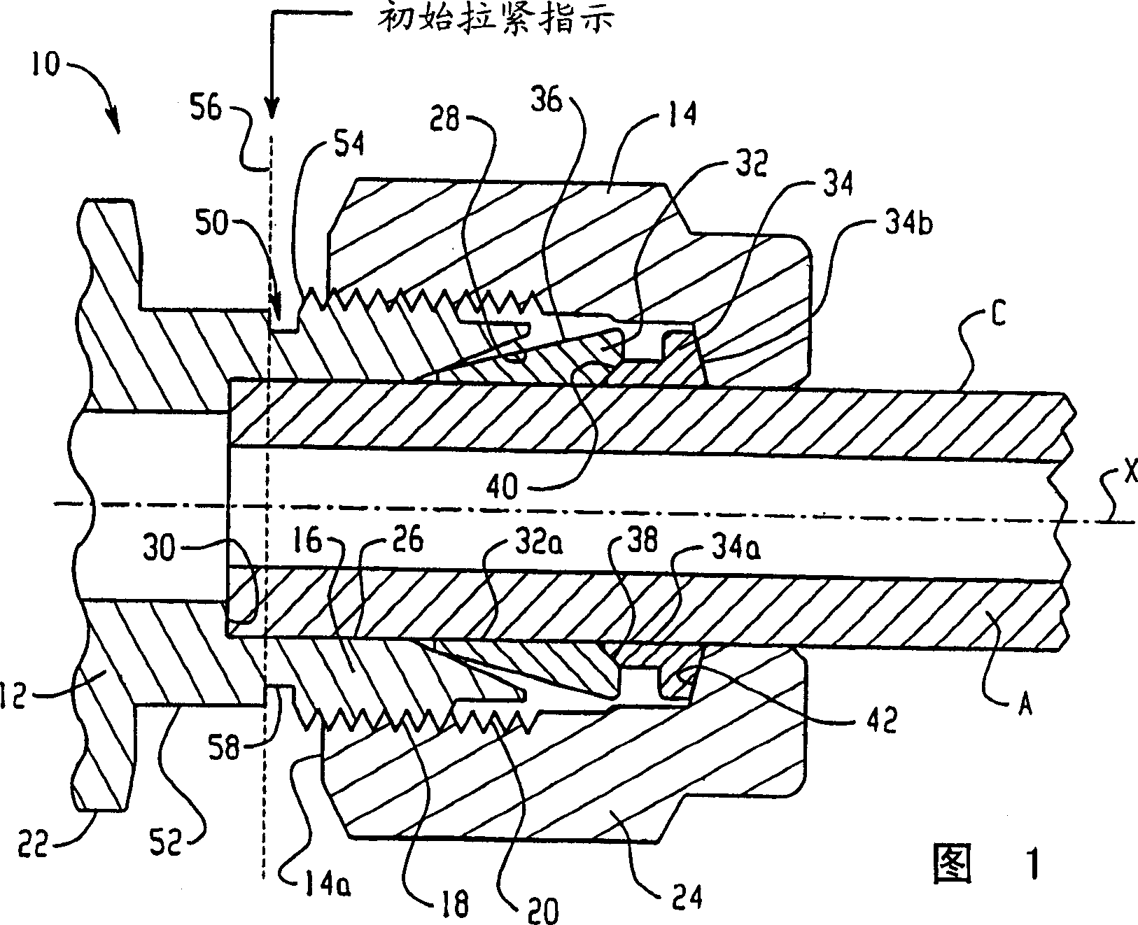
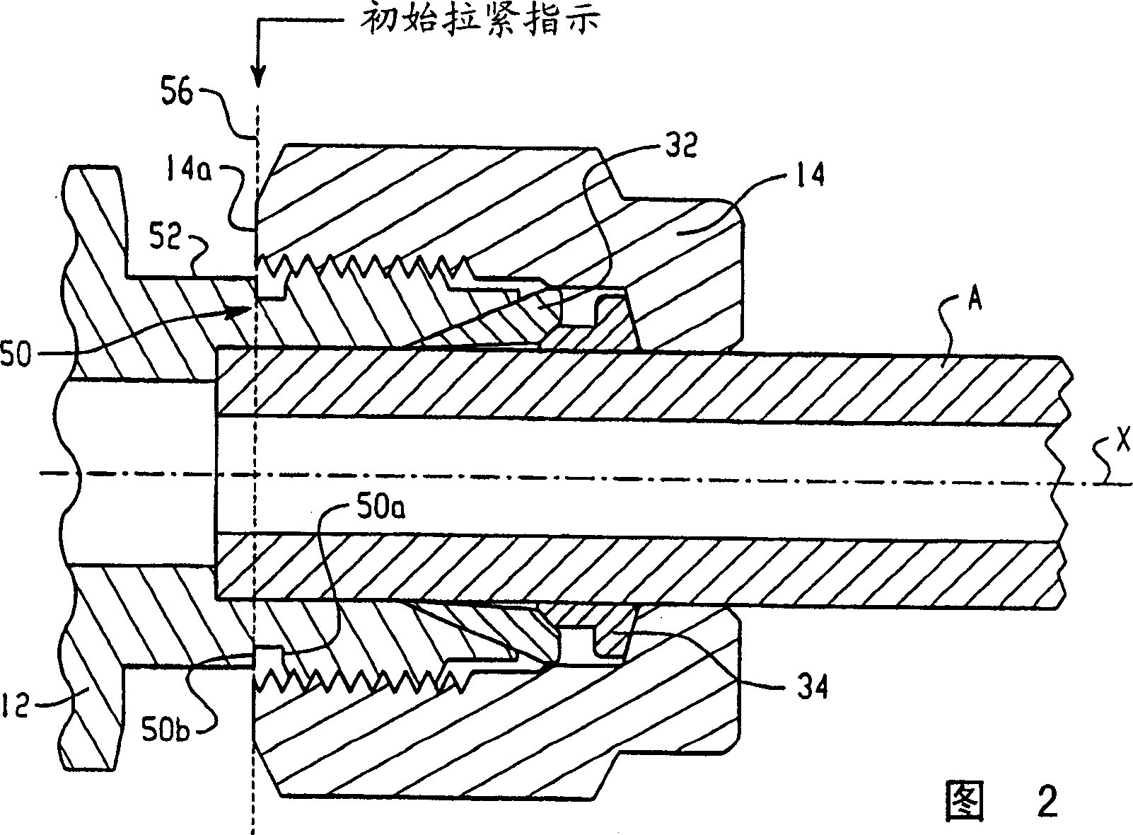
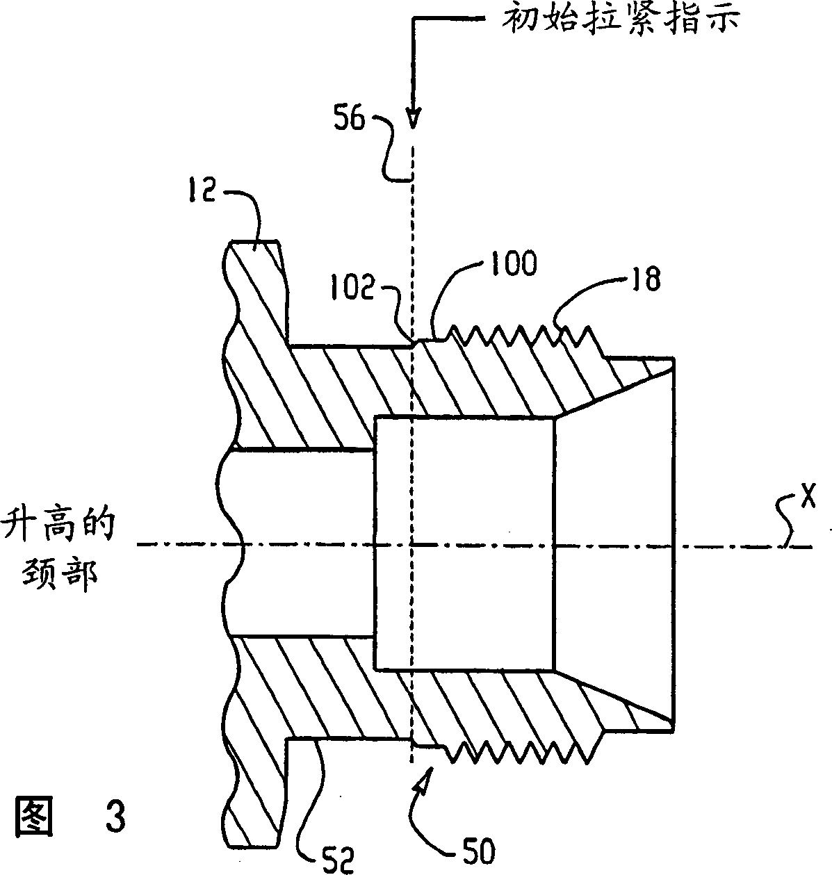
[0044] Referring to Figure 1, the present invention is described herein by way of example in conjunction with a standard two ferrule fitting assembly. However, this description is intended to explain or illustrate the concepts and advantages of the present invention by way of example only, and therefore should not be regarded in a limiting sense. Those of ordinary skill in the art will readily appreciate and appreciate that the present invention may be practiced in a wide variety of fittings and quick-disconnect fittings that are rotated relative to each other for assembly. For example, and not by way of limitation, the present invention may be conveniently used with a single tube fitting or a fitting having any two connectors, where their proper assembly is partially accomplished by relative rotation between the two threaded parts determined.

[0045] A standard fitting assembly 10 includes a fitting body 12 and a fitting nut 14 . The fitting body 12 includes a first end 16...


PUM


Abstract

An intrinsic gauging device for a ferrule type tube fitting of the type having a coupling nut, a coupling body and at least one ferrule, includes a precisely formed marking that has a predetermined relationship with the coupling nut when the fitting has been initially pulled-up. The marking may be realized as a precision groove or recess machined into a surface. The groove can be made more easily visually perceptible such as by roughening, knurling or coloring the surface. The groove defines an edge at a precise position that corresponds to a predetermined axial displacement of the nut relative to the body for initial pull-up. The marking may also be formed with a precise dimension such as an axial length to provide a second edge that corresponds to a predetermined axial displacement of the nut relative to the body beyond initial pull-up for fitting assemblies that are remade.

Description

technical field [0001] The present invention relates to this form of fitting using one or more ferrules for gripping the ends of the pipe. More particularly, the present invention relates to an apparatus and method for visually verifying that a fitting has been properly tensioned. Background technique [0002] Compression fittings are well known in the art. One type of double ferrule joint that has been used with great success for 30 years is the sequential clamping structure, US Patent No. 3,103,373 to Lennon et al., the entire disclosure of which is incorporated herein by reference in its entirety. [0003] A typical ferrule-type fitting assembly has a fitting structure that includes a fitting body and a fitting nut that can be threaded onto one end of the fitting body. The fitting body contains a wrench flange, typically in the form of a hexagonal flange. The other end of the fitting body may be connected to or integrated with another fitting body, flow control device,...

Claims


Application Information

Patent Timeline
IPC IPC(8): F16L19/08F16B31/02F16L19/00F16L19/06F16L19/065
CPCF16L19/00F16L19/103F16L2201/10F16L19/065
Inventor P·C·威廉斯L·E·约翰斯顿J·D·卡科斯拉克G·A·巴布德S·S·莫赫G·W·舍菲尔
Owner SWAGELOK CO
Why Eureka
Try Eureka