Improved cylinder

A cylinder and cylinder barrel technology is applied in the field of improvement of the cylinder structure of a piston engine, which can solve the problems of increased energy consumption, reduced engine service life, blue smoke and the like, and achieves increased energy consumption, reduced service life, and sealing effect. Good results

Inactive Publication Date: 2003-01-15
段华
View PDF0 Cites 5 Cited by
  • Summary
  • Abstract
  • Description
  • Claims
  • Application Information

AI Technical Summary

Problems solved by technology

During the operation of this kind of seal ring, the seal is still good at the beginning stage. After a considerable period of operation, the wear between the piston seal ring and the cylinder will cause the flat opening of the piston seal ring to increase continuously. The structure that blocks the airflow, during operation, the airflow will inevitably flow from the side with high pressure to the side with low pressure through the opening, and the oil will flow upwards from this. When it encounters high temperature, the phenomenon of engine oil burning, blue smoke and carbon deposits will occur. , resulting in a reduction in the power of the engine, an increase in energy consumption, and a reduction in the service life of the engine
[0003] Before the present invention is accomplished, the transportation, loading, hoisting machinery or air compressor of the piston engine identical to the improved cylinder of the present invention have not been seen to be housed in people's daily work, and have not been seen to be equipped with the same as the present invention. The transportation, loading, hoisting machinery or air compressor of the piston engine of the improved cylinder with the same structure of the invention are sold on the market, and there is no record of the improved cylinder identical with the present invention in the literature

Method used


Image

  • Improved cylinder
  • Improved cylinder
  • Improved cylinder

Examples


Embodiment 1

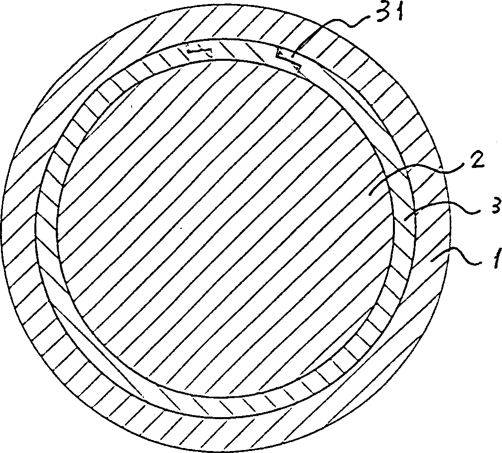
[0032] figure 1 yes figure 2 A-A direction view in ;

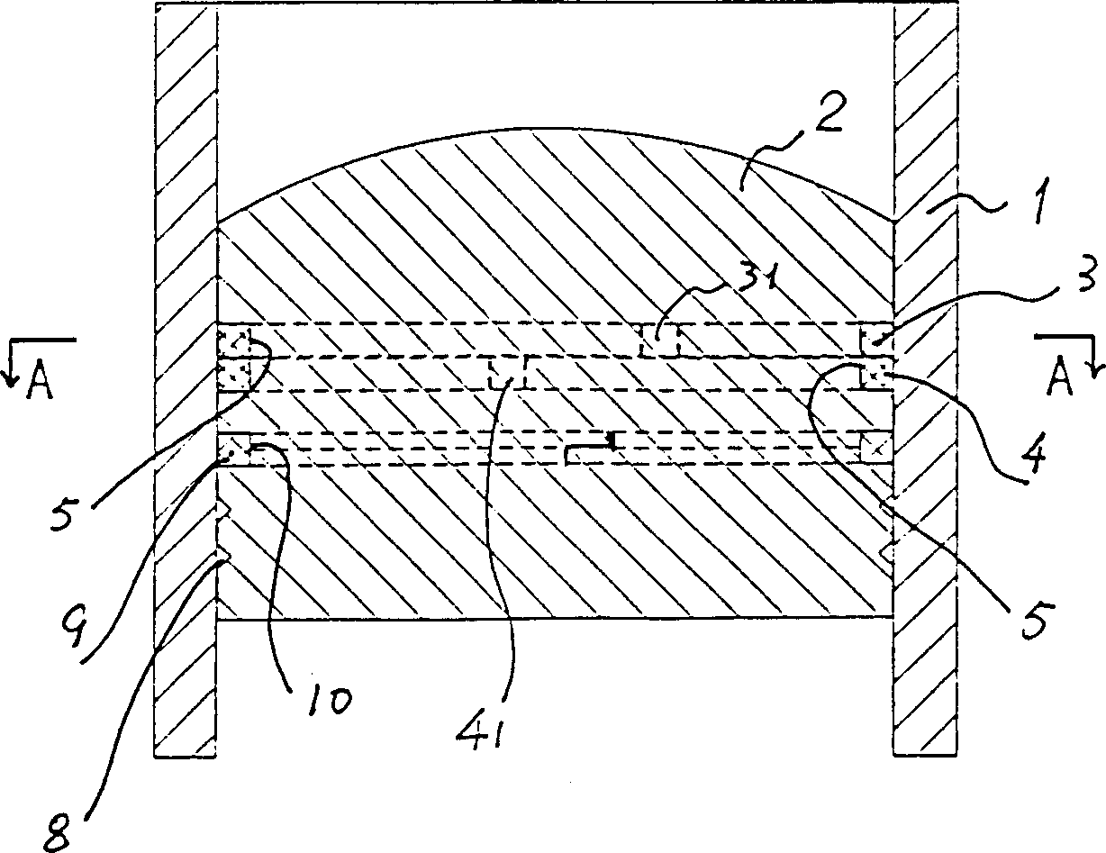
[0033] figure 2 It is a schematic diagram of the structure (part) section front view of the improved cylinder described in Embodiment 1 of the first technical solution of the present invention;

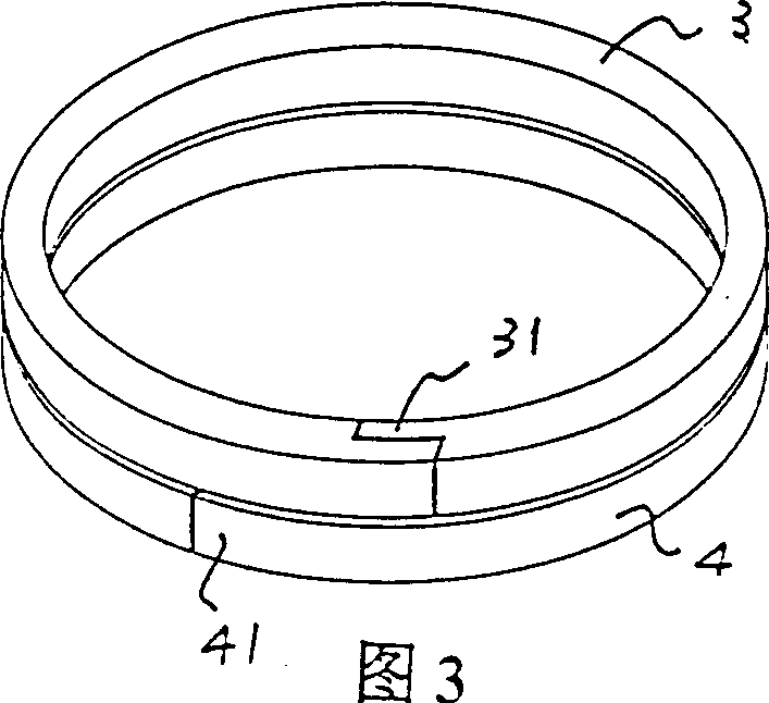
[0034] Fig. 3 is a structural schematic diagram of the piston ring included in the improved cylinder mentioned in Embodiment 1 of the first technical solution of the present invention.

[0035] An improved cylinder, comprising a cylinder barrel (1), a piston (2), a piston ring (3) and an oil ring (9), the piston ring (3) is located in the piston ring groove (5) of the piston, and the oil ring (9 ) is located in the oil ring groove (10) of the piston, which is characterized in that two parallel piston rings (3, 4) are arranged in the said piston ring groove (5), and the piston ring joints (31, 41) are in diameter Upwards, the outer and inner stepped butt joint structures are opposite. The two parallel piston ring joints (31, ...

Embodiment 2

[0037] Figure 4 yes Figure 5 A'-A' in the view;

[0038] Figure 5 It is a schematic diagram of the structure (part) section front view of the said improved cylinder of the second technical solution embodiment 2 of the present invention;

[0039] Image 6 It is a structural schematic diagram of the piston ring included in the improved cylinder mentioned in Embodiment 2 of the second technical solution of the present invention.

[0040]Another improved cylinder comprises a cylinder barrel (1), a piston (2), a piston ring (6) and an oil ring (11), the piston ring (6) is located in the piston ring groove (12) of the piston, and the oil ring ( 11) Located in the oil ring groove (14) of the piston, it is characterized in that two piston rings (6, 7) nested together are arranged in the said piston ring groove (12), and a piston ring joint (61) In the axial direction, it is a stepped butt joint structure facing up and down. The other piston ring joint (71) is a disconnected fl...


PUM


Abstract

An improved cylinder features that two parallel piston rings are in a slot on piston, the joint of piston ring is butt connected in step mode, the joints of two piston rings are staggered. It is possible that two piston rings are sleeved together. Its advantages are high durability and sealing performance, and elongated service life of engine.

Description

Technical field [0001] The invention relates to a piston engine, in particular to the improvement of the cylinder structure of the piston engine. Background technique [0002] The diameter of the piston in the cylinder of the piston engine is consistent with the inner diameter of the cylinder barrel, and there is a sliding connection between them. Under the action of gas pressure, the piston slides reciprocally along the cylinder barrel. On the piston, a piston ring groove is provided, and a piston ring is embedded in the piston ring groove, and an oil storage ring is also arranged on the piston. In the cylinder of the engine currently used, the piston sealing ring generally adopts a flat opening structure. During the operation of this kind of seal ring, the seal is still good at the beginning stage. After a considerable period of operation, the wear between the piston seal ring and the cylinder will cause the flat opening of the piston seal ring to increase continuously. ...

Claims


Application Information

Patent Timeline
Patent Type & Authority Applications(China)
IPC IPC(8): F02F3/04F02F5/00
Inventor 段书礼
Owner 段华
Why Eureka
Try Eureka