Apparatus for detecting sliding contact parts of electric rotary equipment

A technology of sliding contact and electric rotation, applied in the direction of adopting electrical devices, electromechanical devices, measuring devices, etc., can solve the problems of expensive wiring system, time-consuming replacement of carbon brushes, etc., achieve small footprint, avoid the risk of short circuit, and realize convenient maintenance sexual effect

Inactive Publication Date: 2003-02-05
SIEMENS AG
View PDF3 Cites 21 Cited by
  • Summary
  • Abstract
  • Description
  • Claims
  • Application Information

AI Technical Summary

Problems solved by technology

All known systems require expensive wiring systems, e.g. wires from the sensor to the computing unit and test unit outside the brush holder, or e.g. complex compressed air ducts
When replacing the carbon brushes, the pipe must first be removed and then reconnected, which overall results in a time-consuming replacement of the carbon brushes

Method used


Image

  • Apparatus for detecting sliding contact parts of electric rotary equipment
  • Apparatus for detecting sliding contact parts of electric rotary equipment
  • Apparatus for detecting sliding contact parts of electric rotary equipment

Examples


Embodiment Construction

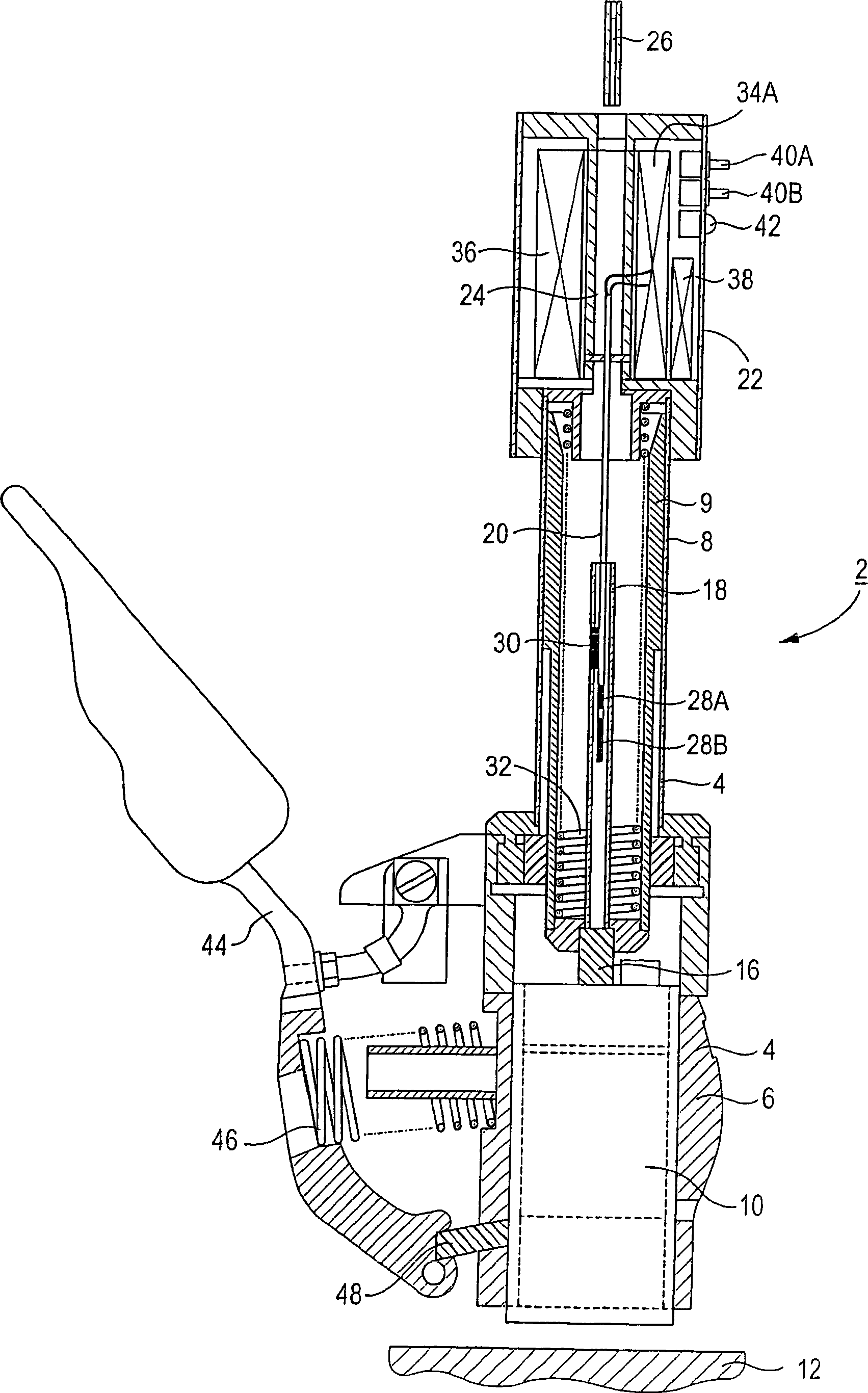
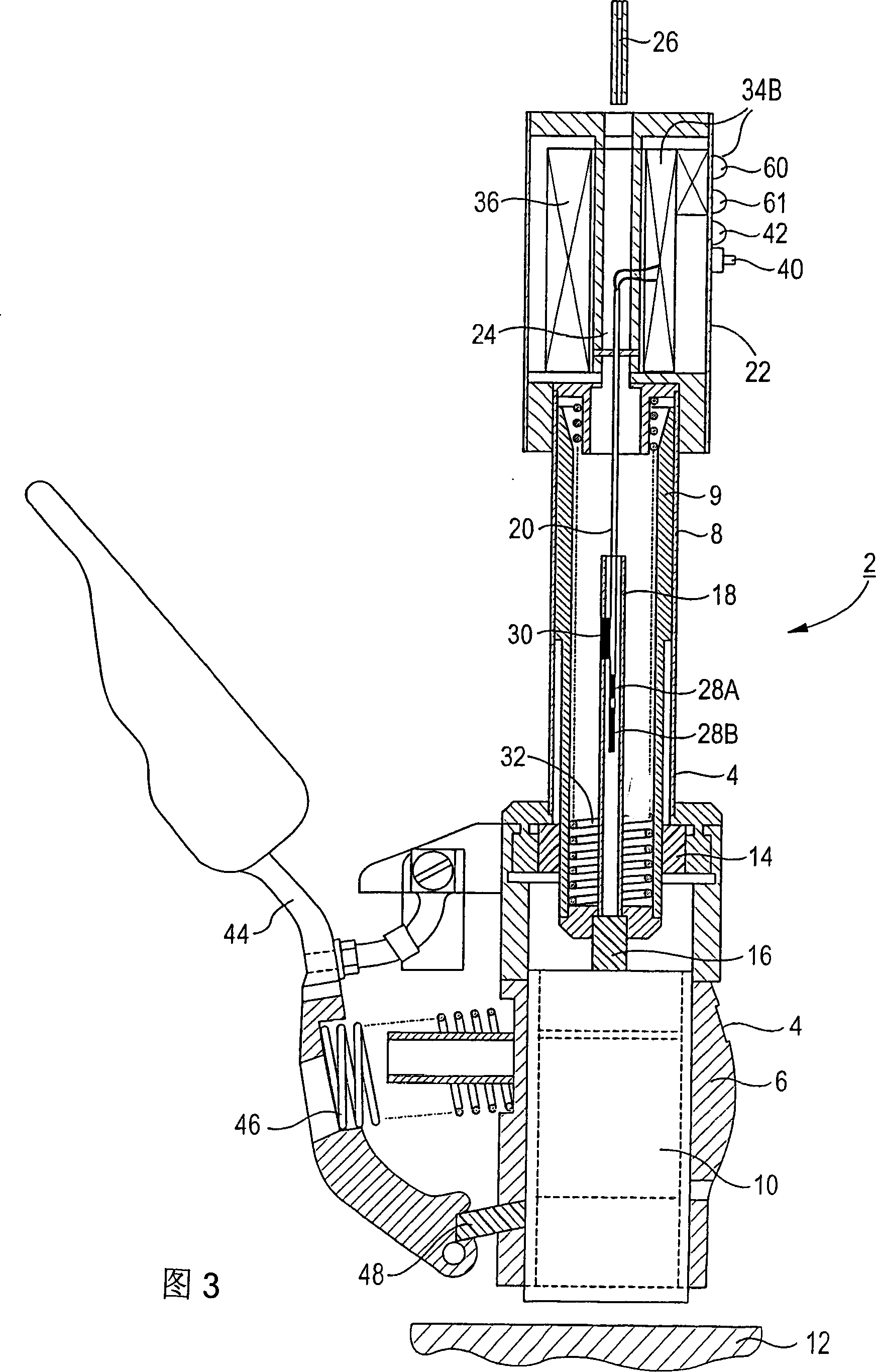
[0039] According to FIG. 1 , the brush holder 2 comprises a housing 4 with a sliding contact sheath 6 at the bottom and a tubular housing part 8 connected to the sheath. A telescopic sleeve 9 is arranged inside the housing part 8 . Sliding contact elements 10 , in particular carbon brushes, are arranged in the sliding contact sheath 6 . The sliding contact element 10 is in contact with the slip ring 12 during operation.

[0040] The telescopic sleeve 9 extends through the end face-defining sleeve 14 of the sliding contact sheath 6 to this sheath. The telescopic sleeve 9 is closed on the end face, and the connecting piece 16 on the telescopic sleeve 9 is pressed against the end of the sliding contact part 10 . A plastic sleeve 18 is arranged on this connecting piece 16 , which is inserted into the telescopic sleeve 9 . The test sleeve 20 again protrudes into the plastic sleeve 18 from above. The sleeve is likewise a tubular structure and is connected to the electronic modul...


PUM


Abstract

An apparatus for monitoring a sliding contact element (10) in an electrical rotating machine, in particular a generator, includes a holder, especially a brush holder (2) and a sensor (28, 30, 68, 70, 72) for detection of a state variable of the sliding contact element (10). An evaluation unit (50) is also provided for evaluation of the state variable which is detected by the sensor (28, 30, 68, 70, 72), with signals from the sensor (28, 30, 68, 70, 72) being transmitted to the evaluation unit (50) without using wires. The wire-free transmission makes the apparatus particularly maintenance-friendly.

Description

technical field [0001] The invention relates to a detection device for detecting sliding contact parts of electric rotating equipment, in particular turbogenerators, the device having a sliding contact part holder and a sensor for acquiring state parameters of the sliding contact part and a A calculation unit that calculates the state parameters acquired by the sensors. Background technique [0002] In particular, the invention relates to a brush-inserted support for a turbogenerator with slip rings or an exciter with collector rings. A carbon brush is inserted into the brush holder as a replaceable sliding contact part. [0003] Electric rotating equipment has field windings on the rotor. The excitation current of the field winding is conveyed through the slip ring through carbon brushes. For generators that deliver electrical energy, the magnitude of the field current depends on the power required. A specific carbon brush current load is req...

Claims


Application Information

Patent Timeline
Patent Type & Authority Applications(China)
IPC IPC(8): G01B7/00G08C17/00G08C23/00H01R39/00H01R39/58H02K11/25H02K11/35
CPCH01R39/58H02K11/25H02K11/35H02K5/14
Inventor 于尔根·克拉尔
Owner SIEMENS AG
Why Eureka
Try Eureka