
Method for using triangular marker in scan location and check

A scanning positioning, triangle technology, applied in the direction of instruments, character and pattern recognition, computer parts, etc., can solve problems such as difficulty in ensuring accuracy, high requirements for calibration boards, and inability to check the correctness of magnification, so as to improve positioning accuracy. The effect of verifying the accuracy and reducing the position accuracy requirements

Inactive Publication Date: 2003-02-12
力捷电脑(中国)有限公司
View PDF0 Cites 5 Cited by
  • Summary
  • Abstract
  • Description
  • Claims
  • Application Information

AI Technical Summary

Problems solved by technology

The calibration method of the above orientation, position and color is relatively simple, and has been used in scanners for many years, and has made positive contributions to the positioning and color correction of scanners. However, with the development of scanner technology, this positioning calibration has exposed Some defects: 1. In order to ensure the accuracy of the scanner, not only the printing quality of the calibration sheet (CalibrationSheet) is required to be high, but also the position where the calibration sheet is pasted is also very high, otherwise it is difficult to guarantee the accuracy
2. Unable to check and correct the correctness of the magnification
3. Unable to measure and correct the slope of the scan line

Method used


Image

  • Method for using triangular marker in scan location and check
  • Method for using triangular marker in scan location and check
  • Method for using triangular marker in scan location and check

Examples


Embodiment

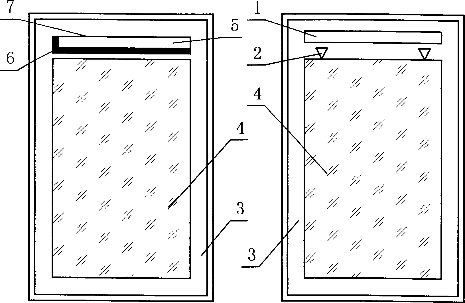
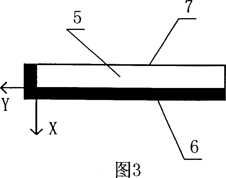
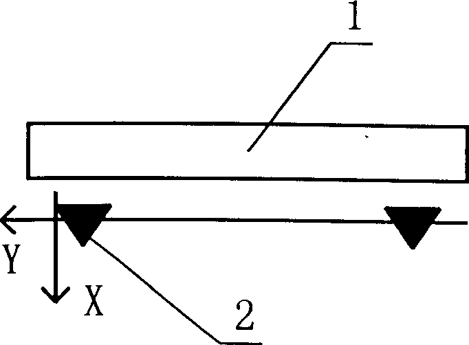
[0034] Example: see attached figure 2 , Figure 4 , as shown in Figures 5 to 7, a method of using triangular marks for scanning positioning verification, firstly, on the upper cover 3 corresponding to the starting position of the optical image system of the scanning head, two identical markings are arranged alternately along the scanning line direction Triangle positioning mark 2, the triangle is an equilateral triangle with a side length of 3 units, see figure 2 As shown, the two same triangular positioning marks 2 are concavely set on the corresponding positions on the back of the upper cover 3 by one-time injection molding, and the reflective surface of the triangular marks 2 forms a certain angle with the back of the upper cover 3, as shown in FIG. 5 . Then paste the calibration whiteboard 1 on the front of the triangular mark 2, and although the calibration whiteboard 1 is still pasted on the back of the upper cover 3 in the form of a label, the accuracy requirements f...


PUM


Abstract

A scan locating and checking method using triangular marker includes such steps as making a concave and a convex triangles at the scan start position on top cover of scanner, creating the X and Y coordinates and position of an optical induction region at the position whose locating characteristic value is associated with the said triangular markers, measuring and correcting the inclination of scanning line by comparing the length of scanning line crossing with two triangles at the same time, and checking and correcting the magnification of optical imaging system by comparing the images of two triangle.

Description

technical field [0001] The present invention relates to a scanning positioning verification method of a scanner, in particular to a method of optical induction positioning verification and whiteness correction of the scanner itself when the scanner is turned on. In the method, two triangles arranged side by side are used as positioning verification marks, Based on this, a new scanning positioning verification method is established. Background technique [0002] The optical sensing system of any scanner must automatically perform positioning verification and whiteness correction when it is turned on, otherwise it is difficult to ensure the accuracy and consistency of the orientation and whiteness of the scanned format during long-term use. The so-called positioning verification is to verify the direction and position of the optical sensing area, in other words, to determine the position of the X and Y coordinates. The so-called whiteness correction is...

Claims


Application Information

Patent Timeline
Patent Type & Authority Applications(China)
IPC IPC(8): G06K9/20G06K9/32
Inventor 林清源吴翔
Owner 力捷电脑(中国)有限公司
Features
  • Generate Ideas
  • Intellectual Property
  • Life Sciences
  • Materials
  • Tech Scout
  • Unparalleled Data Quality
  • Higher Quality Content
  • 60% Fewer Hallucinations
Learn More