

Method and instrument for detecting infrared ascending conversion material
An infrared up-conversion and detection device technology, which is applied in the detection field of infrared up-conversion materials, can solve the problems of anti-counterfeiting failure, inability to further expand the application range of infrared up-conversion materials, and large limitations, and achieve good anti-counterfeiting performance and convenient anti-counterfeiting detection and effective effect
- Summary
- Abstract
- Description
- Claims
- Application Information
AI Technical Summary
Problems solved by technology
Method used
Image

Examples
Embodiment 1
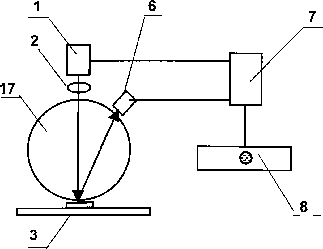
[0036] Embodiment one: see attached image 3 As shown, a detection device for infrared up-conversion materials includes an infrared laser 1, a lens 2, a support frame 17 (an integrating sphere can also be used) and a detector 6. The infrared laser 1 emits an infrared beam (such as 980nm, the range is 850- 1550nm infrared light can be used for excitation), after passing through the lens 2, it is irradiated on the up-conversion material 3, and the focus point is on the surface of the material. Because the intensity of the infrared light at the focus is high, after the material is excited by the high-intensity infrared light, Partially convert the infrared light into visible light. After the visible light is reflected from the surface of the material, the visible light is incident on the detector 6. The detector converts the optical signal into an electrical signal. After conversion and processing, the authenticity is judged on the display 8.
Embodiment 2
[0037] Embodiment two: see attached Figure 4 As shown, a detection device for infrared up-conversion materials includes an infrared laser 1, a lens 2, an integrating sphere 4 (which can also be a support frame) and a detector 6, and the infrared laser 1 emits an infrared beam (such as 980nm, the range is 850- 1550nm infrared light can be used for excitation), after passing through the lens 2, it is irradiated on the up-conversion material 3, and the focus point is on the surface of the material. Because the intensity of the infrared light at the focus is high, after the material is excited by the high-intensity infrared light, The infrared light is partially converted into visible light. After the visible light is reflected from the surface of the material, it enters the integrating sphere 4. At the same time, the visible light is also incident on the narrow-band filter 5. After narrow-band filtering, it is incident on the detector 6. The detector transmits the optical signal ...
Embodiment 3
[0039] Embodiment three: see attached Figure 5 to attach Figure 7 As shown, an infrared up-conversion material detection device includes an infrared laser 1, a lens 2, an integrating sphere 4 and a three-way detector. The infrared laser 1 emits an infrared beam, which is irradiated on the up-conversion material 3 after being focused by the lens 2. , the focal point is on the surface of the material. After the material is excited by high-intensity infrared light, part of the infrared light is converted into visible light. After the visible light is reflected from the surface of the material, it enters the integrating sphere 4. At the same time, the visible light also enters the narrow-band filter 5, 9 After being filtered by a narrow band, it is incident on the detectors 6 and 10, and the detector converts the optical signal into an electrical signal, and after A / D conversion and processing by a single-chip microcomputer chip, the intensity ratio on each detector is obtained,...
PUM
 Abstract
Description
Claims
Application Information