Display

a technology of display and vapor deposition, applied in the field of display, can solve the problems of cumbersome steps, large equipment and cost, and inability to accurately align the printing on both surfaces, and achieve the effect of enhancing the coloring effect in the structure area and high visibility

Active Publication Date: 2016-01-07
TOPPAN PRINTING CO LTD
View PDF8 Cites 12 Cited by
  • Summary
  • Abstract
  • Description
  • Claims
  • Application Information

AI Technical Summary

Benefits of technology

[0045]The structure areas having transmittance of not less 20% can provide a display exerting high visibility under transmitted light observation. Further, the structure areas are combined with non-structure areas having transmittance of not more than 20%. This allows the

Problems solved by technology

Further, vapor deposition of a multilayer film involves complicated steps and thus takes time and effort.
However, correct alignment in performing printing on both surfaces incurs large equipment and cost.
Accordingly, there is a necessit

Method used


Image

  • Display
  • Display
  • Display

Examples


example 1

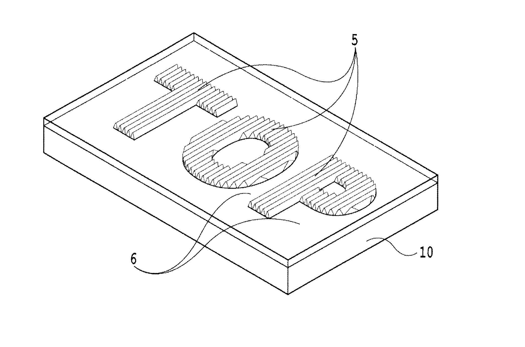
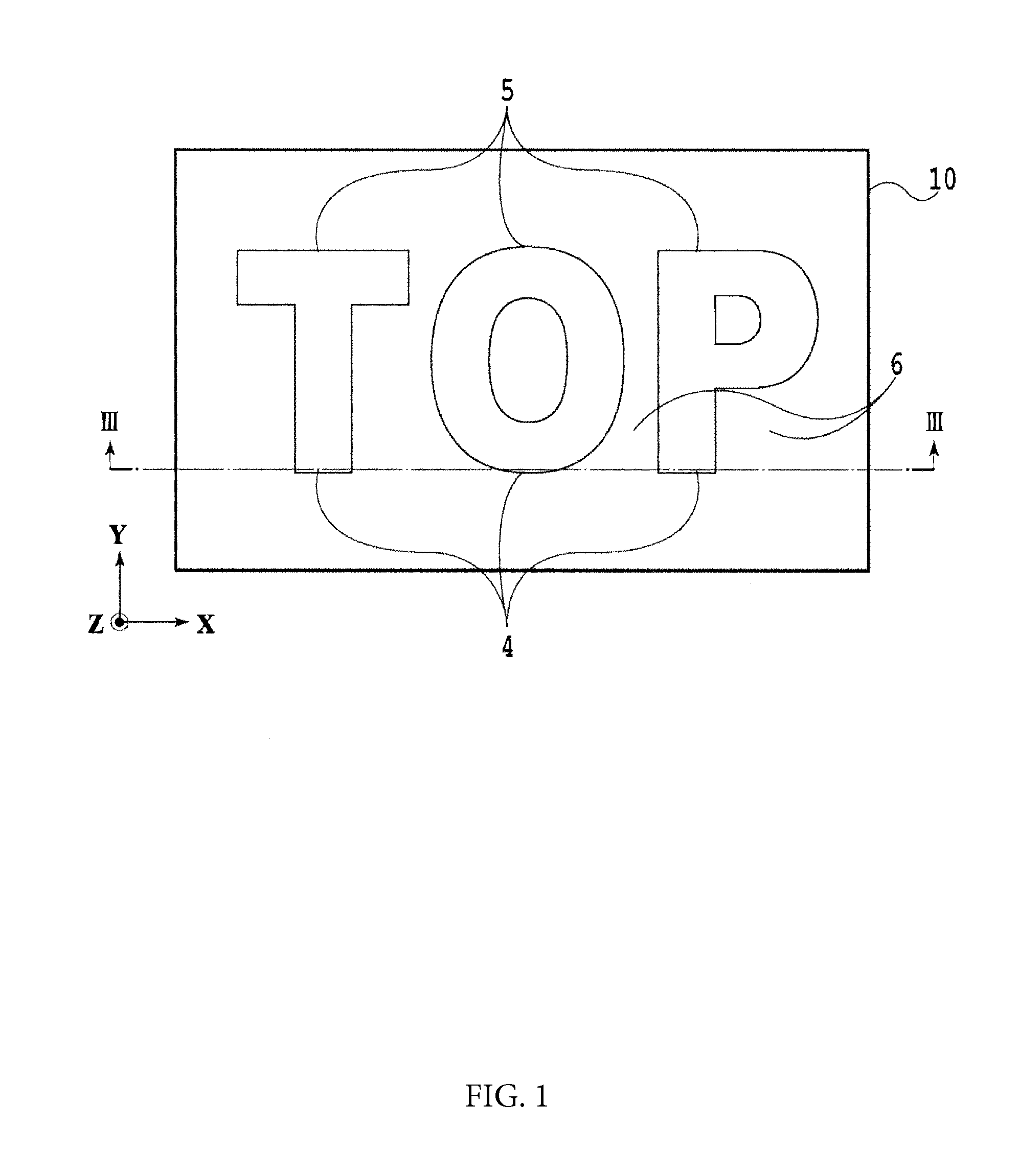
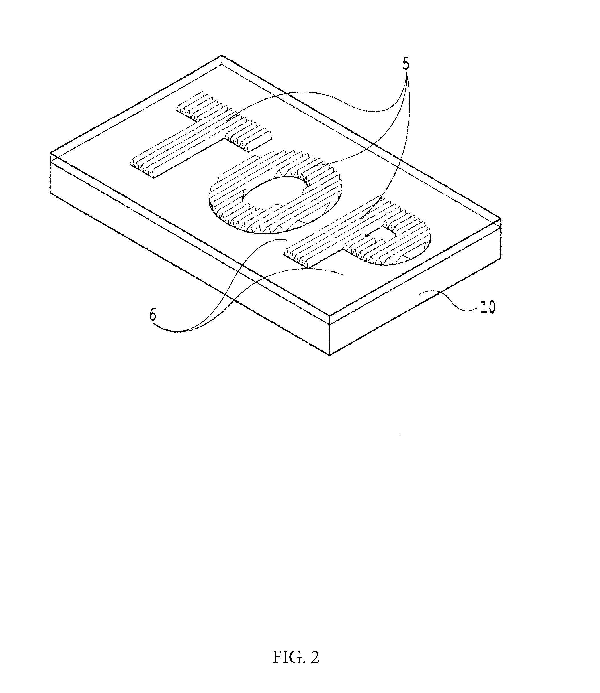
[0137]FIGS. 17 and 18 schematically illustrate an example of the display of the present invention. The display 10 includes a polyethylene terephthalate (PET) film as the transparent base 1, an ultraviolet curable resin as the structure-forming layer 2, and a diffraction grating with the cycle P and the height H of the order of several hundred nm as the concavo-convex structures 4 arranged in the respective structure areas 5. A plurality of structure areas 5 are provided having respective concavo-convex structures 4 which have different cycles P and heights H.

[0138]In the example shown in FIG. 17, the structure areas 5 are provided as designs in the form such as of a star or a crescent. The structure areas 5 may be provided in any pattern. Further, the method for forming the diffraction grating used for the concavo-convex structures 4 may be a method using a laser exposure / interference system, or the diffraction grating may be formed by electron beam drawing, or the like.

[0139]The li...

example 2

[0144]As the transparent base 1, a polyethylene terephthalate (PET) film was used. As the transparent forming layer 2, an ultraviolet-curable resin was used. As the concavo-convex structures 4 arranged in the respective structure areas 5, a diffraction grating having the cycle P of 300 to 600 nm and the height H of 100 nm to 500 nm was formed.

[0145]A plurality of combinations of the structure areas of different heights were provided and the cycles P were ensured to be different between the combinations. The diffraction grating used for the concavo-convex structures 4 was formed by electron beam drawing. A film of the light reflection layer 3 was formed by forming an aluminum deposition layer using a vacuum vapor deposition method.

[0146]The transparent member 8 was formed on the protective layer 7. By adhering the transparent member 8 and the protective layer 7, the display 10 integrated with the transparent member 8 was obtained. As the transparent member 8, a PET film thicker than ...


PUM


Abstract

A display includes a transparent base having one surface on which a structure-forming layer, a light reflection layer and a protective layer are sequentially laminated. The light reflection layer reflects part of the incident light, while transmitting therethrough the rest of the light. The structure-forming layer includes a plurality of structure areas, and each of the plurality of structure areas is formed of a concavo-convex structure.

Description

CROSS-REFERENCE TO RELATED PATENT APPLICATIONS[0001]This application is a continuation application filed under 35 U.S.C. 111(a) claiming the benefit under 35 U.S.C. 120 and 365(c) of PCT International Application No. PCT / JP2014 / 001223, filed Mar. 5, 2014, which is based upon and claims priority to Japan Priority Application 2013-049426, filed Mar. 12, 2013 and Japan Priority Application 2013-118648, filed Jun. 5, 2013 and Japan Priority Application 2013-126655, filed Jun. 17, 2013, the entire contents of them all are hereby incorporated herein by reference.BACKGROUND[0002]The present invention relates to a display for preventing counterfeiting or copying of valuable stock certificates, such as gift tickets, or public documents, such as passports. The present invention further relates to a display which facilitates authenticity judgment with the naked eye and performs a function of preventing counterfeiting with high security, and to an information medium provided with the display.[0...

Claims


Application Information

Patent Timeline
IPC IPC(8): G02B5/18B42D25/328G02B1/14G02B5/02G02B27/14
CPCG02B5/1842G02B27/14B42D25/328G02B5/021G02B5/1814G02B1/14B42D25/333B42D25/47B42D25/373
Inventor TSUKAHARA, TOSHIYUKISHINODA, KOICHIHAYASHI, TAKAYOSHI
Owner TOPPAN PRINTING CO LTD
Why Eureka
Try Eureka