

Molded product recovering plant
A technology for recycling devices and molded products, applied in the direction of coating, etc., can solve the problem of unable to solve the problem of molded product collection, unable to realize the separation function, attached to the surface of the mold, or attached to the mold clamping device below the mold opening area Problems on the surface or other parts of the chute
Inactive Publication Date: 2003-02-26
NISSEI PLASTIC IND CO LTD
View PDF0 Cites 5 Cited by
- Summary
- Abstract
- Description
- Claims
- Application Information
AI Technical Summary
Problems solved by technology
[0002] Molded products made of LCP (Liquid Crystal Polymer) may be charged when they are released from the mold, and thin-walled lightweight molded products on the order of 0.01 to 0.03 g, such as small, narrow-pitch connectors, etc., may be Attached to the surface of the mold under the action of static electricity, or attached to the surface or other parts of the chute installed under the mold opening area of the clamping device, so that it cannot fall into the recycling container under the action of its own weight
[0003] This sticking phenomenon can be alleviated by blowing out strong ionized air that also has the function of unloading, however, although the air flow can blow the moldings off the mold, it cannot solve the problem of collecting the scattered moldings
In the case of "quality recognition conversion chute", it is possible to receive a signal from the molding machine before recycling, thereby separating qualified molded products from bad molded products. At this time, it is unfavorable for scattered molded products to adhere to the chute Yes, because moldings will attach and stay halfway before reaching the separation device; in this way, good moldings and bad moldings will be mixed inappropriately, so that the separation function cannot be achieved
Method used
View moreImage
Smart ImageViewing Examples

Examples
Embodiment Construction
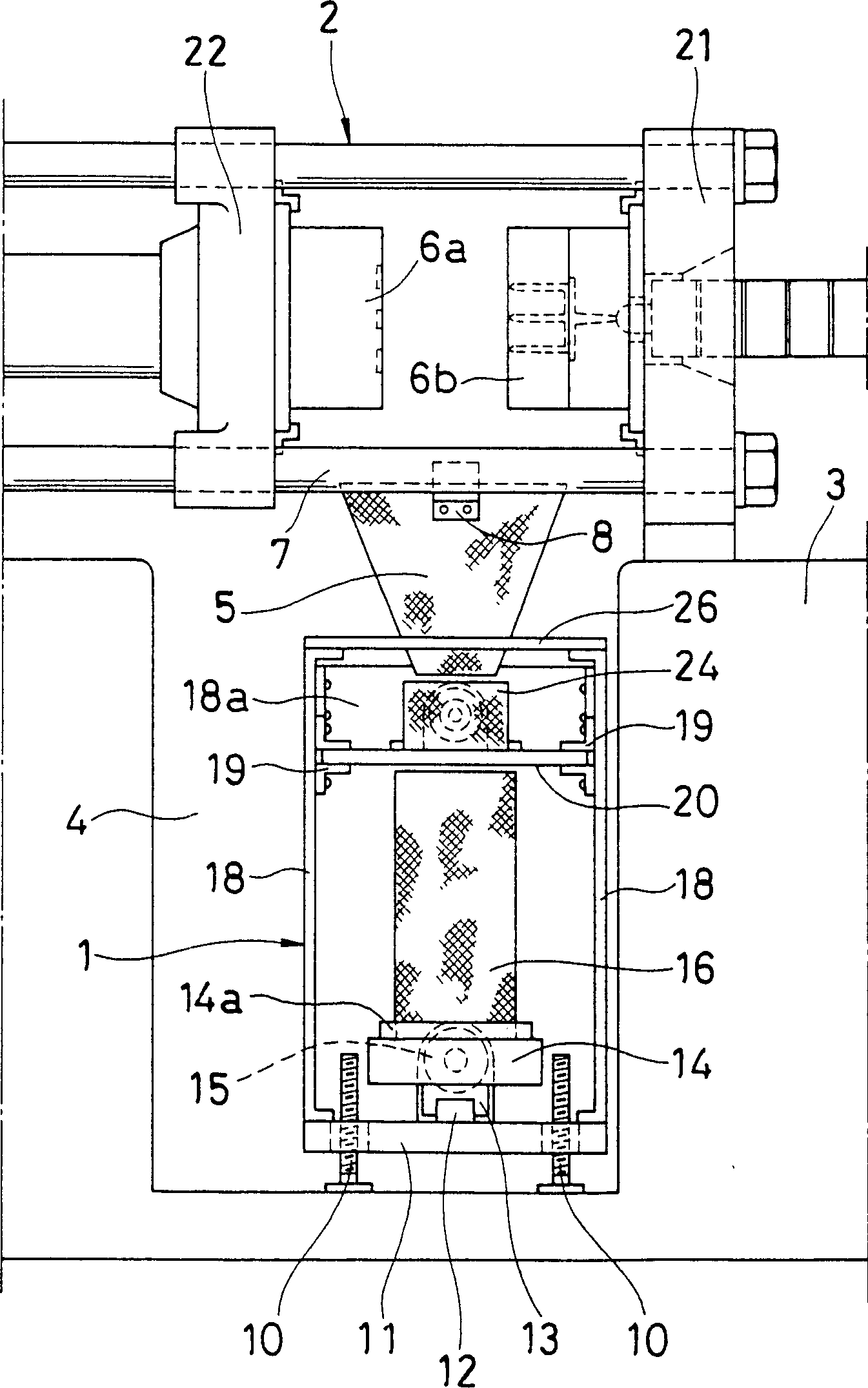
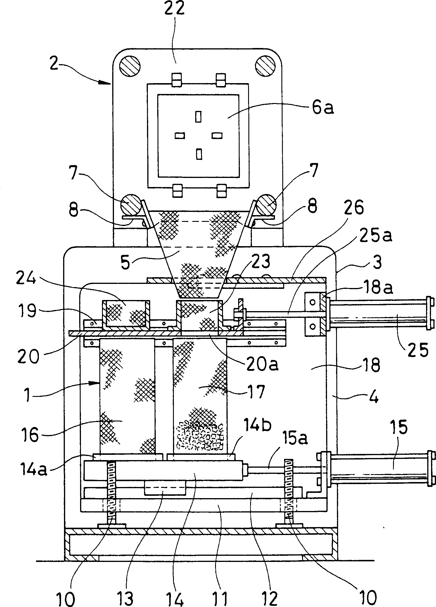
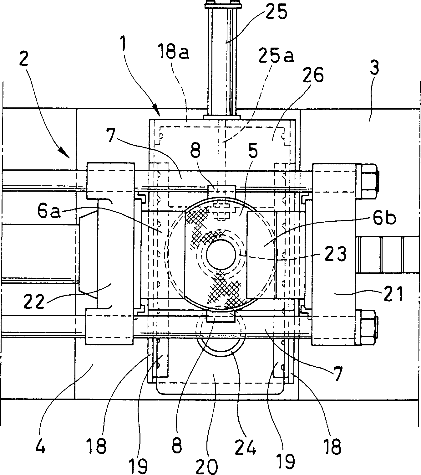
[0011] In the drawings, reference numeral 1 denotes a recovering device installed in a groove 4 of the base 3 formed below the mold opening area of the fixed platen 21 and the movable platen 22 of the clamping device 2 .
Login to View More PUM
 Abstract
Thin and light molded parts released from a die are prevented from sticking by static electricity, by forming the recovery chute of molded part with wire gauze. A moving plate 14 is installed reciprocally movable on an installation plate 11 that can be received in a machine base recess 4 under the die opening area of a mold clamp apparatus 2. A plurality of recovery receptacles 16, 17 are installed detachably on the top face of the moving plate 14. A switching plate 20 having a through hole 20a is installed slidably on the upper portion of the recovery receptacle. A molded part introduction tube 23 of molded parts is installed on the top face of the switching plate superposing on the through hole. A recovery cup 24 of rejected molded parts is juxtaposed to the introduction tube. A hopper shaped chute 5 of molded parts made of fine mesh wire gauze is installed on the introduction tube upper portion. Air cylinders 15, 25 reciprocally move respectively the moving plate and switching plate. The recovery receptacle and introduction tube and recovery cup, or othersare made respectively by forming into a cylindrical shape.
Description
technical field [0001] The invention relates to a molding recovery device for the reliable collection of demoulded thin-walled, lightweight and electrostatically charged moldings, in particular small moldings. Background technique [0002] Molded products made of LCP (Liquid Crystal Polymer) may be charged when they are released from the mold, and thin-walled lightweight molded products on the order of 0.01 to 0.03 g, such as small, narrow-pitch connectors, etc., may be Attached to the surface of the mold under the action of static electricity, or attached to the surface or other parts of the chute installed under the mold opening area of the clamping device, so that it cannot fall into the recycling container under the action of its own weight. [0003] This adhesion phenomenon can be alleviated by blowing out strong ionized air that also has the function of unloading. However, although the air flow can blow the molded products off the mold, it cannot solve the problem of...
Claims
Login to View More Application Information
Patent Timeline
 Patent Type & AuthorityApplications(China)
IPC IPC(8): B29C45/40B29C37/00B29C45/17
CPCB29C37/0003B29K2105/0079B29C45/1769
Inventor井原広一河原信行
OwnerNISSEI PLASTIC IND CO LTD