
Back lighting for LCD

A liquid crystal display and backlighting technology, applied in lighting devices, lighting and heating equipment, instruments, etc., can solve problems such as inability to generate uniform discharge and uneven luminescence

Inactive Publication Date: 2003-03-12
LG DISPLAY CO LTD
View PDF1 Cites 5 Cited by
  • Summary
  • Abstract
  • Description
  • Claims
  • Application Information

AI Technical Summary

Problems solved by technology

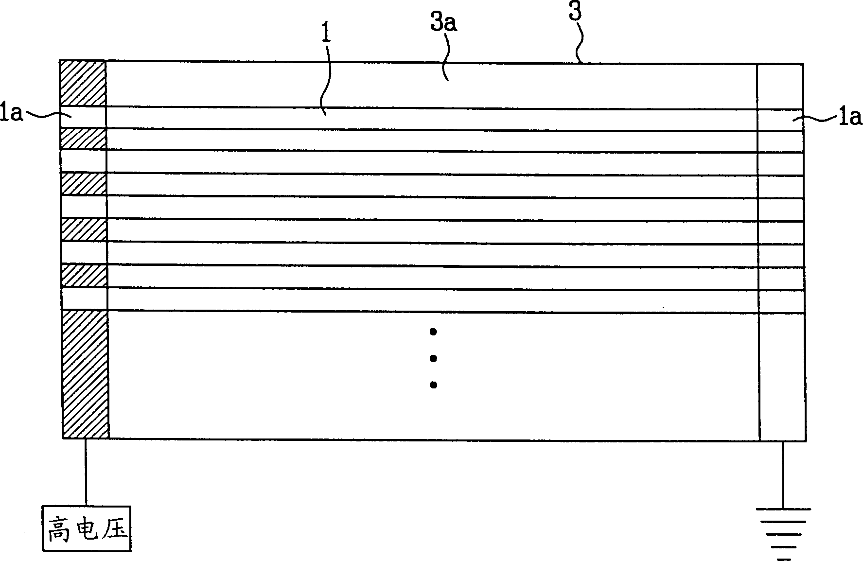
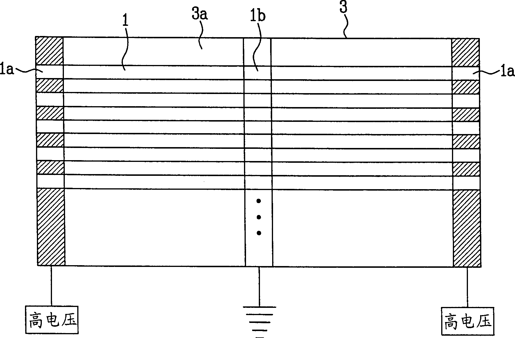
However, even if the two sides of the middle part have the same length, it is still impossible to generate a uniform discharge on both sides
Therefore, there is a problem with non-uniform light emission

Method used


Image

  • Back lighting for LCD
  • Back lighting for LCD
  • Back lighting for LCD

Examples


Embodiment Construction

[0032] Illustrative embodiments of the invention, examples shown in the accompanying drawings, will now be described in detail. Wherever possible, the same reference numbers will be used throughout the drawings to refer to the same or like parts.

[0033] Figure 4 is a plan view of a backlight according to a first embodiment of the present invention. Figure 5A to Figure 5C are perspective views illustrating various examples of a backlight according to the first embodiment of the present invention.

[0034] Such as Figure 4 As shown, the backlight according to the first embodiment of the present invention includes: a plurality of light emitting lamps 10 having electrodes 10b and 10c at both ends of an outer tube 10a; a first frame 20 supporting Glowing lamp 10. First support members 20 a and second support members 20 b are respectively formed at both ends and the center of the first frame 20 to support the electrodes 10 b and 10 c of the light emitting lamp 10 . The light...


PUM

PropertyMeasurementUnit
lengthaaaaaaaaaa
sizeaaaaaaaaaa

Abstract

A back light includes a first case having a plurality of first and second support members, the first support members at ends of the case and the second support member at a center portion of the case and a plurality of luminescent lamps having tubes supported by the first and second support members, having electrodes at both ends of the tubes. The luminescent lamps are arranged alternately at left and right sides of the second support member.

Description

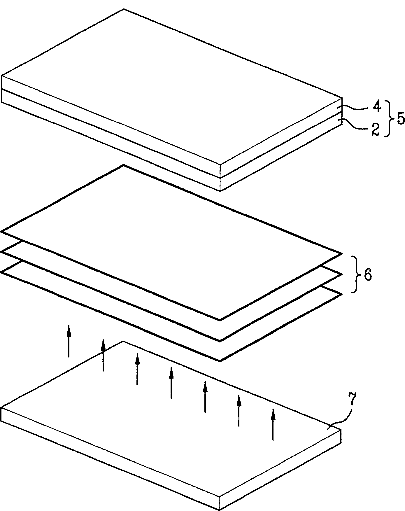
technical field [0001] The present invention relates to a backlight, in particular to a direct backlight for liquid crystal display (LCD) devices. Background technique [0002] In general, ultra-thin sized flat panel displays having a thickness of several centimeters or less, especially flat panel LCD devices, are widely used in monitors for notebook computers, spaceships, and aircraft. [0003] Since there is no light source in this LCD device itself, it is necessary to provide a backlight at the rear of the liquid crystal panel. This backlight is used as a light source. Generally speaking, as shown in Figure 1, the LCD device includes: a liquid crystal panel 5 comprising first and second substrates 2 and 4; a backlight 7 behind the liquid crystal panel 5; a backlight 7 between the liquid crystal panel 5 and the backlight 7 One or more scattering sheets 6. [0004] The backlight 7 serving as a light source for the LCD consists of a cylindrical light emitting lamp. Backl...

Claims


Application Information

Patent Timeline
Patent Type & Authority Applications(China)
IPC IPC(8): F21S2/00F21Y103/00G02F1/13357
CPCG02F1/133604G02F2001/133613G02F1/133608G02F1/133613G02F1/1335
Inventor 林茂宗
Owner LG DISPLAY CO LTD
Learn More