
Plasma display

A plasma display and phase separation technology, applied in solid cathode parts, cold cathode tubes, etc., can solve the problems of poor bonding between carbon nanotube layers and MgO layers, low working efficiency, easy to fall off, etc., to improve driving efficiency, reduce Manufacturing costs and the effect of simplifying the manufacturing process

Inactive Publication Date: 2007-07-18
LG ELECTRONICS(NANJING) PLASMA CO LTD
View PDF0 Cites 0 Cited by
  • Summary
  • Abstract
  • Description
  • Claims
  • Application Information

AI Technical Summary

Problems solved by technology

However, it has the disadvantage of poor bonding between the carbon nanotube layer and the MgO layer and it is easy to fall off
The process is divided into two stages, and there is a weakness of low work efficiency

Method used


Image

  • Plasma display
  • Plasma display

Examples


Embodiment Construction

[0039] Embodiments of the present invention will be described in detail below with reference to the accompanying drawings.

[0040]

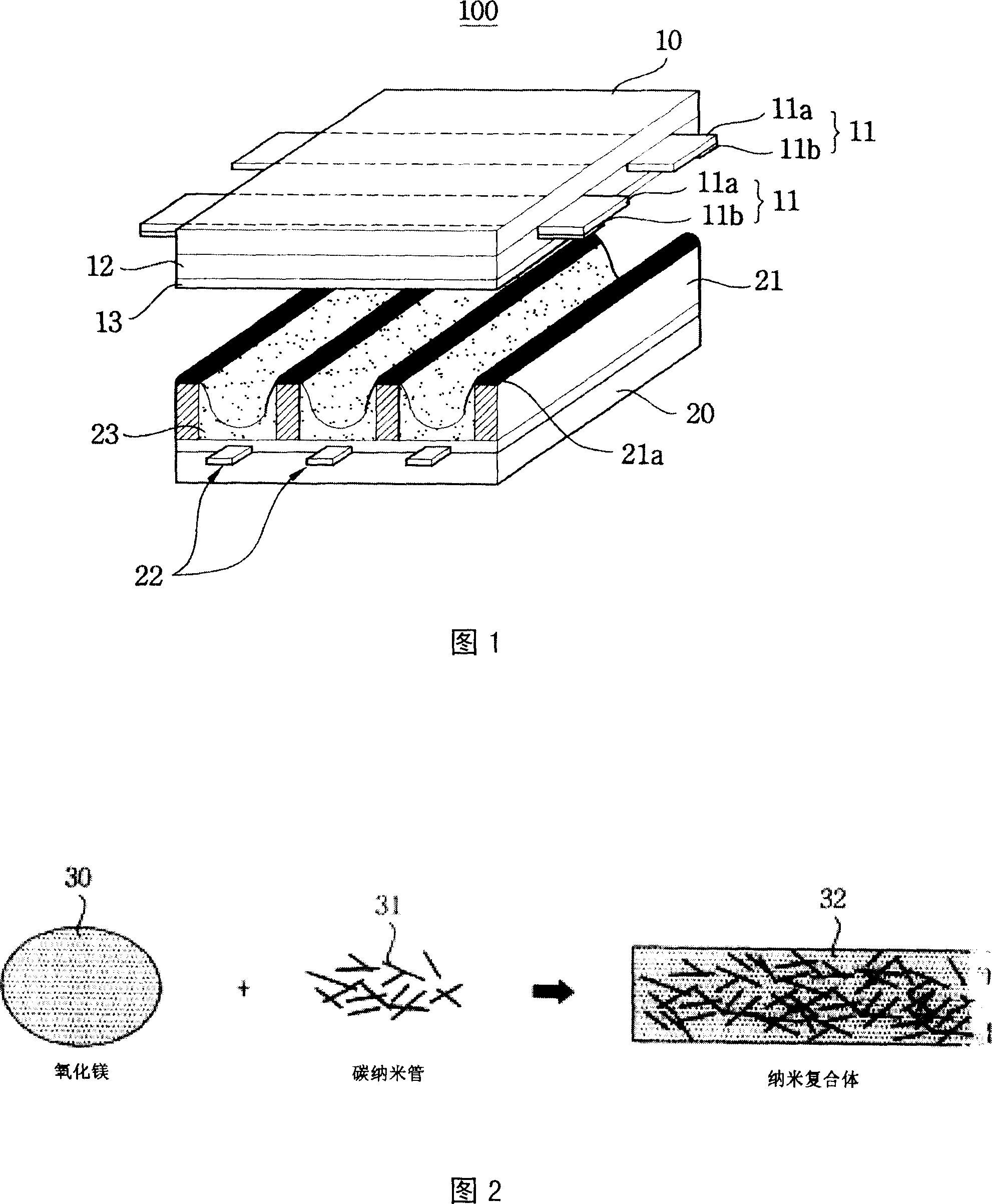
[0041] Fig. 2 is a conceptual diagram of formation of a nanocomposite using carbon nanotubes and MgO.

[0042] As shown in Fig. 2, the MgO solution formed by the sol-gel process and the carbon nanotubes are mixed to form a nanocomposite. That is, carbon nanotubes are added to the liquid MgO material formed by the sol-gel process, and mixed so that the two materials exist uniformly in the nanocomposite to form a nanocomposite. The present invention uses the nanocomposite mentioned here as the raw material of the protective film, so the strong mechanical properties of carbon nanotubes can be used to solve the traditional problem of poor mechanical properties of the protective film. A complex is formed to form a protective film, which solves the traditional problem that the carbon nanotubes and the MgO layer are separated to form a protective fi...


PUM


Abstract

A plasma display with isolation layer and protection film is featured as forming protection film by composite material of magnesium oxide and carbon nanotube and coating formed film on face plate of plasma display for generating large amount of secondary electron.

Description

technical field [0001] The present invention relates to plasma displays, and more particularly to plasma displays including protective films formed from nanocomposites. Background technique [0002] There are several types of flat panel displays that have attracted much attention recently, including liquid crystal displays, plasma displays, and induction EL displays. Among the display devices currently on the market, liquid crystal displays are mainly used for medium and small size displays, and plasma displays are mainly used for large displays. [0003] Generally, in a plasma display (Plasma Display Panel: hereinafter referred to as 'PDP'), a partition wall formed between a front glass and a rear glass made of soda-lime glass forms a unit cell, and each cell Neon (Ne), helium (He) or a mixture of neon and helium (Ne+He) is used as the discharge gas inside, and when the inert gas with a small amount of xenon (Xe) is discharged according to high-frequency voltage, vacuum ul...

Claims


Application Information

Patent Timeline
Patent Type & Authority Applications(China)
IPC IPC(8): H01J17/49H01J17/02
Inventor 金货年郑珉在
Owner LG ELECTRONICS(NANJING) PLASMA CO LTD
Learn More