Reflective projecting apparatus

A projector and reflective technology, applied in the field of reflective projectors, can solve problems such as difficult alignment of optical axes

Inactive Publication Date: 2003-03-26
SAMSUNG ELECTRONICS CO LTD
View PDF1 Cites 3 Cited by
  • Summary
  • Abstract
  • Description
  • Claims
  • Application Information

AI Technical Summary

Problems solved by technology

When the optical distance is extended, the diameter of the projection lens unit decreases, and the slope of the FLCD increases, making it difficult to align the optical axis between the FLCD and the projection lens unit

Method used


Image

  • Reflective projecting apparatus
  • Reflective projecting apparatus
  • Reflective projecting apparatus

Examples


Embodiment Construction

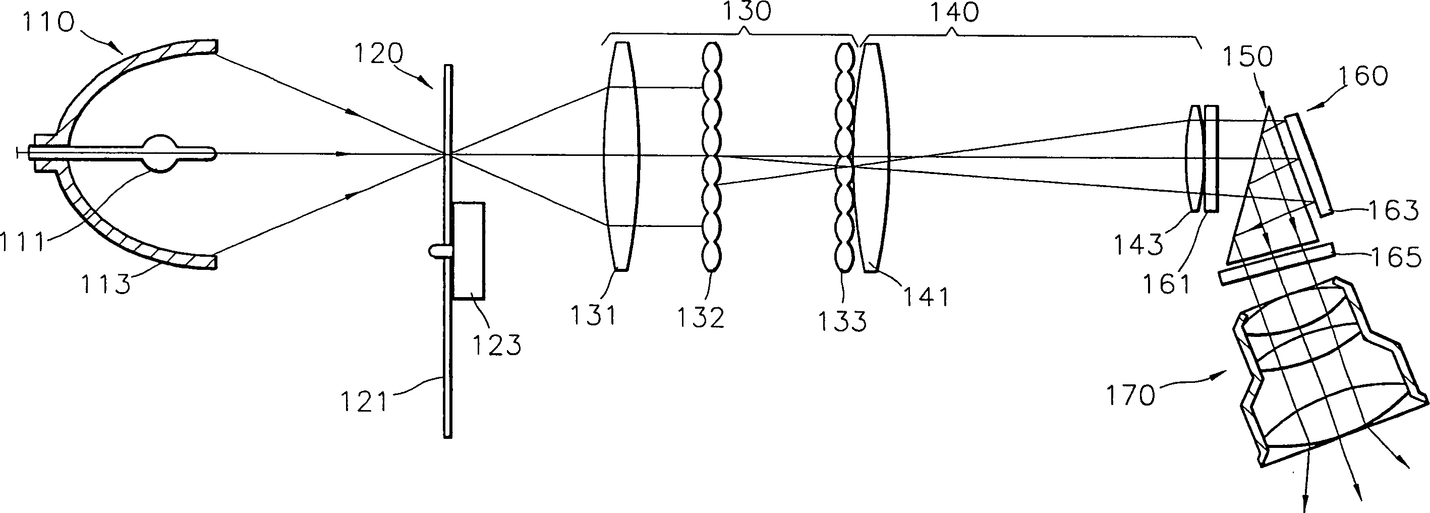
[0025] refer to Figure 2-4 , the reflective projector of the first embodiment of the present invention includes: a light source 110 for generating and emitting light; a color filter 120 for selectively transmitting specific wavelengths of light emitted by the light source 110 to select colors; An image forming unit 160; a critical angle prism 150 for transmitting the incident light from the light source 110 to the image forming unit 160 and reflecting the incident light of the image forming unit 160; and a projection lens unit 170 for transmitting the incident light Magnified and projected onto a screen (not shown).

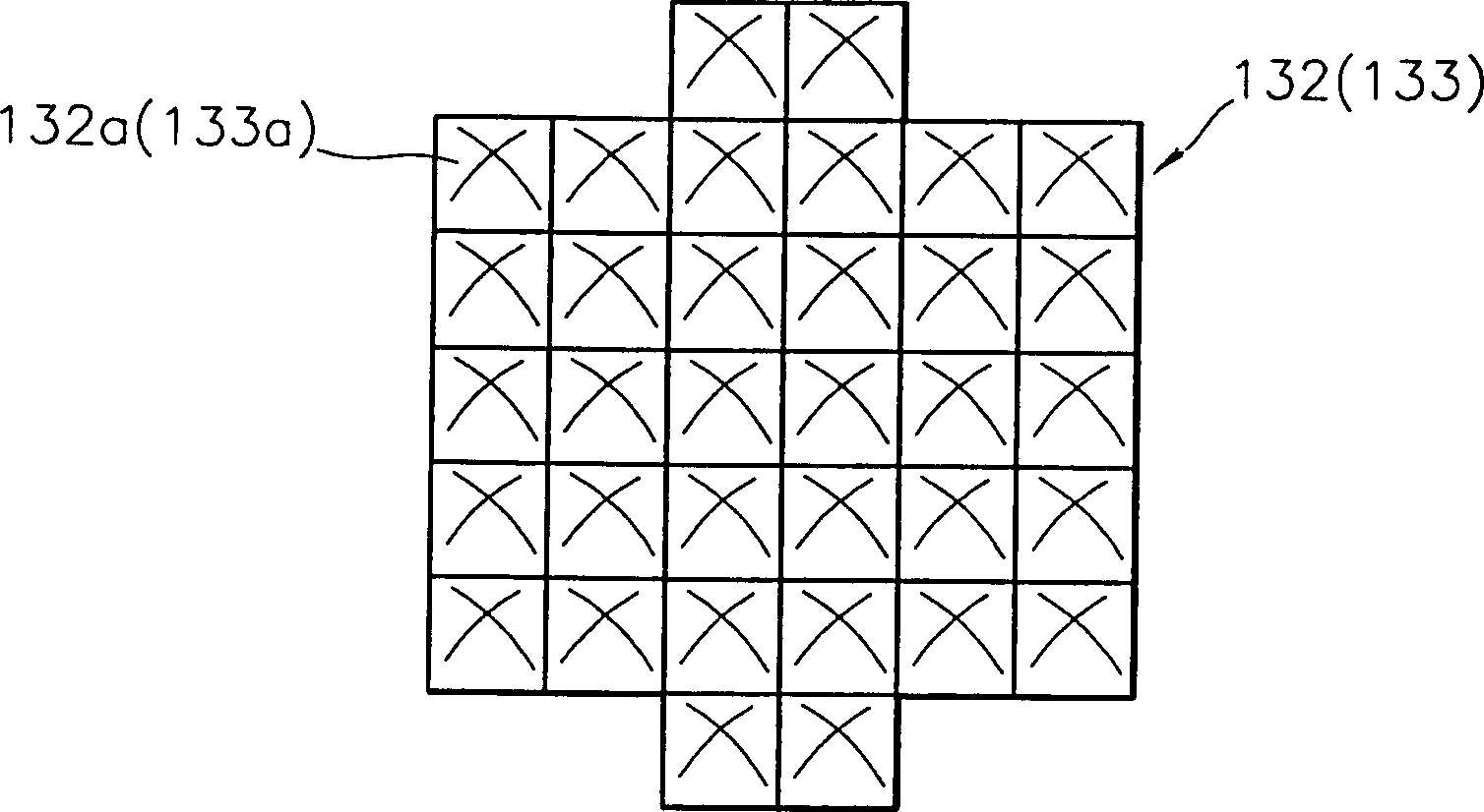
[0026] Preferably, the optical path between the color filter disc 120 and the critical angle prism 150 also includes: a light mixing unit 130 for diverging / converging or scattering and reflecting the incident light from the light source 110 to make the light uniform; The relay lens 140 is used to converge the incident light to form a parallel light beam.

[00...


PUM


Abstract

A reflection type projector including a critical angle prism for changing the path of light. The reflection type projector includes a light source for generating and emitting light, an image forming unit having a multiplicity of pixels in a two-dimensional array structure, each of the pixels being independently driven, for forming and reflecting an image from the input light, a critical angle prism having a transmission / reflection surface disposed along an optical path of the light, to transmit the light input from the light source and reflect the light re-entering from the image forming unit, and a projection lens unit for enlarging and transmitting the light reflected from the transmission / reflection surface of the critical angle prism onto a screen.

Description

[0001] This application is a divisional application of an invention patent application whose application date is April 7, 1998, application number 98106226.1, and the applicant is Samsung Electronics Co., Ltd., and the invention name is "reflective projector". technical field [0002] The present invention relates to a reflective projector using a reflective display device, in particular to a reflective projector capable of increasing the intensity of light projected onto a screen. Background technique [0003] A projector is a device that displays images by projecting a shaped image on a screen using an additional light source. Projectors are classified as projection-type projectors or reflection-type projectors according to how images are formed. [0004] figure 1 The optical system of a conventional reflective projector is shown. As shown in the figure, a conventional reflective projector includes a light source 10 for emitting light; a color filter 20 for transmitting ...

Claims


Application Information

Patent Timeline
Patent Type & Authority Applications(China)
IPC IPC(8): G02F1/13G02B27/18G02F1/1335G03B21/00H04N5/74H04N9/31
CPCH04N9/3197H04N5/7458H04N9/315H04N5/74H04N5/7441
Inventor 崔舜喆
Owner SAMSUNG ELECTRONICS CO LTD
Why Eureka
Try Eureka