Fastening clamping assembly and connecting structure therewith

A technology for connecting structures and fixtures, applied in the direction of connecting components, furniture connections, connections, etc., can solve problems such as joint failure

Inactive Publication Date: 2003-04-02
MODULAR SYST
View PDF2 Cites 18 Cited by
  • Summary
  • Abstract
  • Description
  • Claims
  • Application Information

AI Technical Summary

Problems solved by technology

Therefore, these joints fail prematur...

Method used


Image

  • Fastening clamping assembly and connecting structure therewith
  • Fastening clamping assembly and connecting structure therewith
  • Fastening clamping assembly and connecting structure therewith

Examples


Embodiment Construction

[0060] Specific implementation

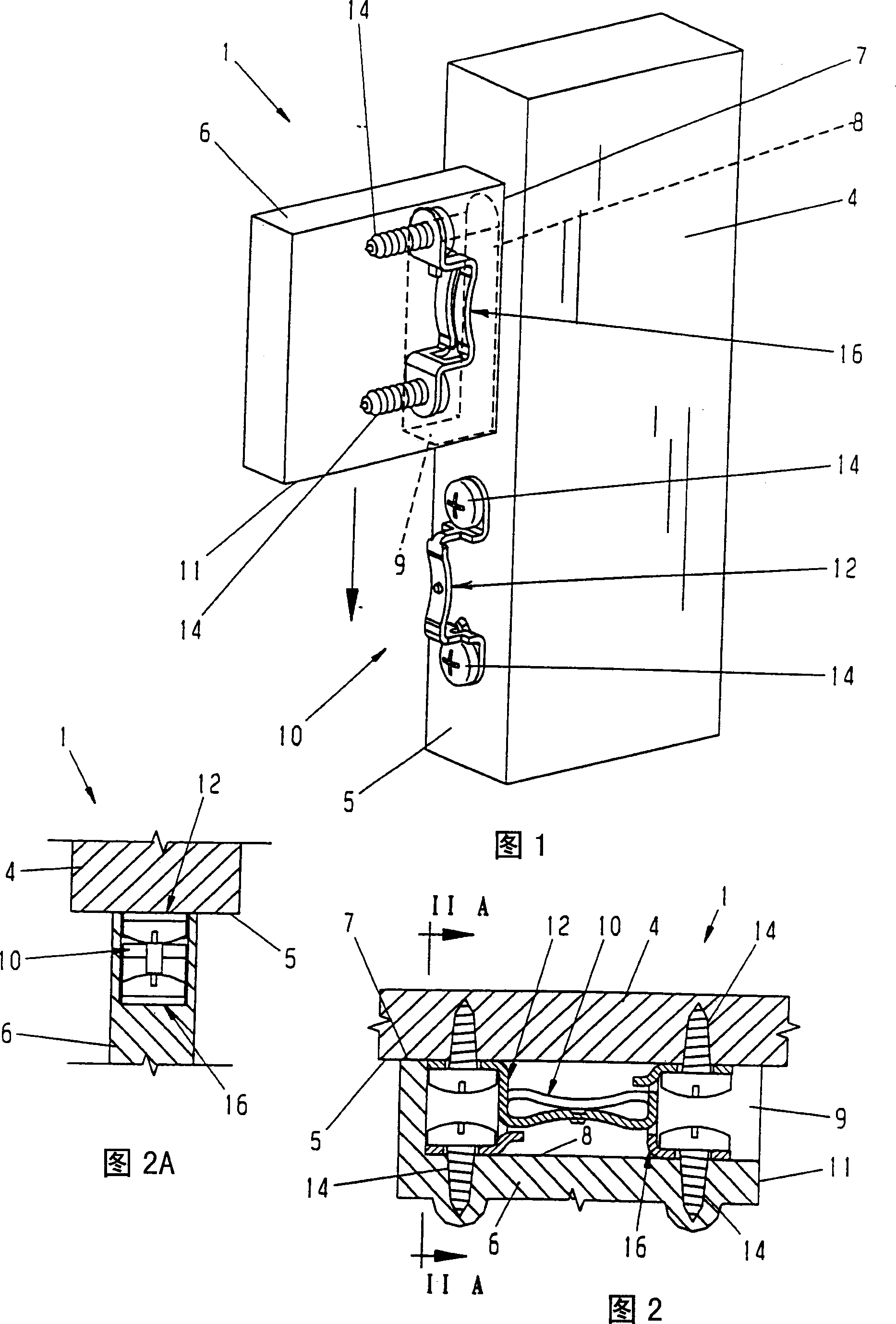
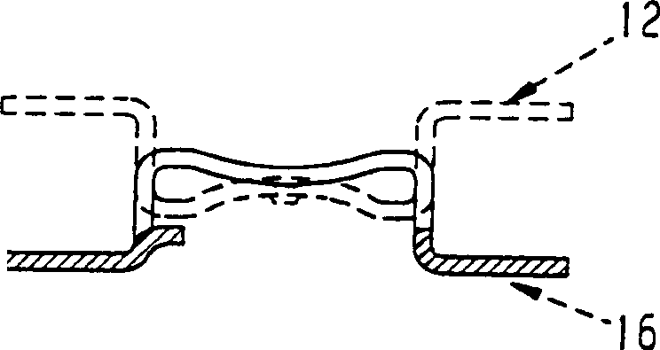
[0061] Figures 1, 2 and 2A show a typical connection structure 1 in which the clamp assembly 10 of the present invention is used, such as a furniture assembly, in this case the legs or supports 4, beams or horizontal supports of tables, chairs, etc. 6 can be installed on it by the present invention. The vertical support or leg 4 includes a side 5 on which one of the two parts of the clamp assembly 10 (in this case a convex clamp) is fixed by a screw 14. The horizontal support or beam 6 includes a distal edge 7 in which a pocket or groove 8 is formed, the groove 8 having a bottom surface, and the second part of the clamp assembly 10 (in this case a slotted concave clamp 16 ) Is still fixed on the bottom surface by a pair of mounting screws 14. The pocket 8 has a window or opening 9 extending through the vicinity of the beam 6 or the bottom surface 11 so that, as described more fully below, when the beam 6 is moved downward, the clamps 12 and 16 enga...


PUM


Abstract

A fastener clip assembly for forming a substantially concealed joint between panels of furniture, a shelf assembly or the like includes a pair of clips telescopingly assembled with one another to form a joint which prevents rotation between the clips and joint members. The clips are secured to respective joint members and assembled with a portion of the second clip received through the slot of the first clip such that offset engagement sections overlap one another while a resilient, flexible inclined section on at least one, but preferably both, of the engagement sections draws the clips and joint members together. An engaging member which resists disassembly of the clips may be included.

Description

Technical field [0001] The present invention relates to fastening for connecting one connecting part or panel or another connecting part or panel in furniture, racks, storage bins, shelves, public telephone booths, room dividers, decorative panels, frames, storage devices, etc. The system, more specifically, relates to a fastening clip assembly for forming a connection between connecting parts or panels of these structures. Background technique [0002] For example, many connections between modern furniture components are fastened together by concealed mechanical connections. Many of these concealed fasteners use keyhole-type slits and stud-shaped fasteners. Generally, this type of fastening system includes short grooved areas along the edges of the connecting parts to be connected together, such as furniture panels. One or more fasteners are installed in one connecting part or piece of furniture, and stud bolts are installed in the other. The fastener engages the head of the stu...

Claims


Application Information

Patent Timeline
IPC IPC(8): F16B5/00F16B12/00F16B12/20
CPCF16B12/20F16B5/0044F16B12/00Y10T24/45812Y10T403/7111Y10T403/7123Y10T403/7105Y10T292/0999F16B2200/205
Inventor 蒙哥马利·J·韦尔奇凯文·M·维格
Owner MODULAR SYST
Why Eureka
Try Eureka