Fluid composition concentration test method and device thereof

A concentration measurement and fluid technology, which is applied in the field of fluid composition concentration measurement and devices, and can solve the problems of high atmospheric composition and inapplicability.

Inactive Publication Date: 2003-04-02
NIPPON SANSO CORP
View PDF0 Cites 14 Cited by
  • Summary
  • Abstract
  • Description
  • Claims
  • Application Information

AI Technical Summary

Problems solved by technology

However, since it is necessary to install a window formed of a material such as quartz that transmits light in the infrared range on the cell, it is necessary to install large-scale equipment when measuring high-pressure gas.
In addition, in principle, since the components to be measured are limited to infrared active components, there is a high possibility that atmospheric components such as oxygen and nitrogen will be mixed in from the outside, and there is a disadvantage that it is not suitable for component measurement that requires monitoring.

Method used


Image

  • Fluid composition concentration test method and device thereof
  • Fluid composition concentration test method and device thereof
  • Fluid composition concentration test method and device thereof

Examples


no. 1 example

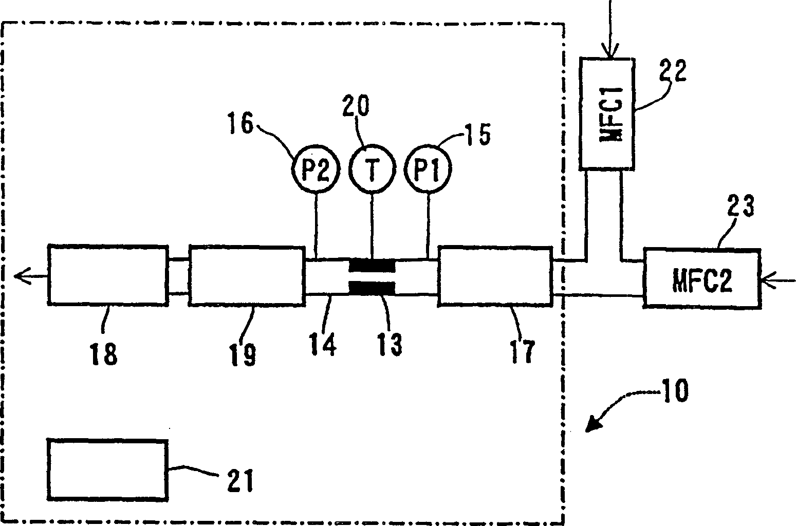
[0065] use as Figure 9 The experimental setup shown. In this experimental device, a pipe provided with a needle valve (UVCIILM manufactured by Motoyama Seisakusho) 13b was used as the pipe for measurement. The first flow controller 22 for introducing krypton (Kr) and nitrogen (N 2 ) The second flow controller and back pressure regulating valve (UR7340B manufactured by STEC) 17a for introduction, and the flow controller (mass flow controller: SEF4400 manufactured by STEC, heat conduction type mass flow meter) 19 is installed downstream.

[0066] The opening degree of the needle valve 13b is set to be appropriate, the back pressure regulating valve 17a is set to a state of 145Kpa, and the two flow controllers 22 and 23 are operated to change the mixing ratio of krypton and nitrogen, and the flow rate after each mixing ratio passes through the needle valve 13b Measured with flow controller 19. The mixing ratio of krypton and nitrogen (Kr / N 2 ) is related to the flow output of...

no. 2 example

[0067] use as Figure 11 The experimental setup shown. This experimental device uses the experimental device of the first embodiment, plus an upstream side pressure measuring device 15 for measuring the pressure on the upstream side of the needle valve 13b, and a downstream side of the flow measuring device 19 for measuring the pressure on the downstream side of the needle valve 13b. A pressure measuring device 16 and a temperature measuring device as a temperature measuring means of the needle valve 13b.

[0068] The pressure difference between the front and rear of the needle valve 13b was set at a fixed value of 45Kpa, and 100% pure nitrogen was continuously supplied for about 16 hours. Meanwhile, the flow output of the flow measuring device 19 is expressed as Figure 12 . Moreover, the temperature change of the needle valve 13b measured by the temperature measuring device 20 at this time is as follows: Figure 13 . Furthermore, the relationship between measured temper...

no. 3 example

[0070] Using the same experimental device as the second embodiment, the temperature of the needle valve 13b is fixed at 25°C, 100% pure argon gas is introduced, and the pressure difference between the front and back of the needle valve 13b is changed to 100KPa, 200KPa, and 300KPa at intervals of 30 minutes , measure the flow output at this time. This result is as Figure 16 shown. Moreover, the relationship between differential pressure and flow output is as Figure 17shown. It can be seen from the results that there is a positive correlation between the pressure difference and the flow output, and the correlation coefficient in this case is 3.73. Then, this correlation coefficient is multiplied by the pressure difference from the reference pressure difference of 300KPa, and the pressure correction of the flow output is performed by multiplying it by the flow output at this time. The result is as Figure 18 shown.

[0071] From the above description, according to the pre...


PUM


Abstract

A method and an apparatus for measuring the concentrations of the components of a fluid are described, which can be used to measure the concentrations of the components continuously in real time and to monitor a high pressure gas, and is suitably used for in-line monitoring. In the method and the apparatus, a fluid sample is conducted through a measuring tube, wherein the measuring tube has a small aperture with a constant diameter in a fluid flow path. The pressure difference (P1-P2) between the upstream and the downstream of the small aperture and the flow rate at the downstream of the small aperture are measured to determine the concentrations of the components of the fluid.

Description

technical field [0001] The present invention relates to a method and device for determining the concentration of fluid components, in particular to a method and device capable of rapid and continuous determination. Background technique [0002] In various manufacturing processes in the field of gas manufacturing or the field of semiconductor manufacturing, the need for low-cost and real-time management of the concentration of gas or liquid has increased. For example, in a gas separation device, since the gas concentration at the inlet is different from the gas concentration at the outlet, the gas component concentration at the inlet and outlet is continuously measured, and the product gas concentration can be managed by changing the operating conditions of the gas separation process . When controlling the component concentration of gas or liquid according to this, the concentration of the fluid component which is continuously measured is obtained. Especially in the field o...

Claims


Application Information

Patent Timeline
Patent Type & Authority Applications(China)
IPC IPC(8): G01N9/26G01F1/42G01F1/68G01N7/00G01N11/02G01N30/62
CPCG01N30/62G01N7/00G01N11/02
Inventor 佐藤哲也吴尚谦君岛哲也
Owner NIPPON SANSO CORP
Why Eureka
Try Eureka