Grinding pad

A polishing pad and foam technology, which is applied in the field of polishing pads, can solve the problems of difficult to achieve, difficult to achieve hardness, and unstable grinding amount.

Inactive Publication Date: 2003-04-02
ROGERS INOAC CORP
View PDF1 Cites 30 Cited by
  • Summary
  • Abstract
  • Description
  • Claims
  • Application Information

AI Technical Summary

Problems solved by technology

However, the former method is difficult to achieve due to changes in physical properties, i.e., changes in the viscoelasticity of the pad during grinding
The latter approach also has drawbacks: because it is difficult to achieve a predetermined hardness
However, this method has disadvantages: if the polishing pad made of polyurethane foam is used, the surface temperature will rise instantaneously due to the friction with the surface of the object to be ground during grinding.
As a result, the viscoelasticity of the surface of the polishing pad changes, making the polishing rate, that is, the polishing amount per unit time, unstable.

Method used


Image

  • Grinding pad
  • Grinding pad
  • Grinding pad

Examples


Embodiment Construction

[0021] Hereinafter, the polishing pad of the present invention will be further described in detail with reference to preferred embodiments. The inventors found that while molding a gas-dissolved raw material by reaction injection molding, which is obtained by dissolving an inert gas in a polyurethane-based raw material, resistance to Urethane-based foams that are preferably used as polishing pads are capable of maintaining excellent polishing rates and step elimination properties subject to changes in polishing conditions. The inventors have also found that using aromatic diamines, for example as crosslinking agents, makes it possible to suppress changes in viscoelasticity, which depends on the temperature of polyurethane-based foams.

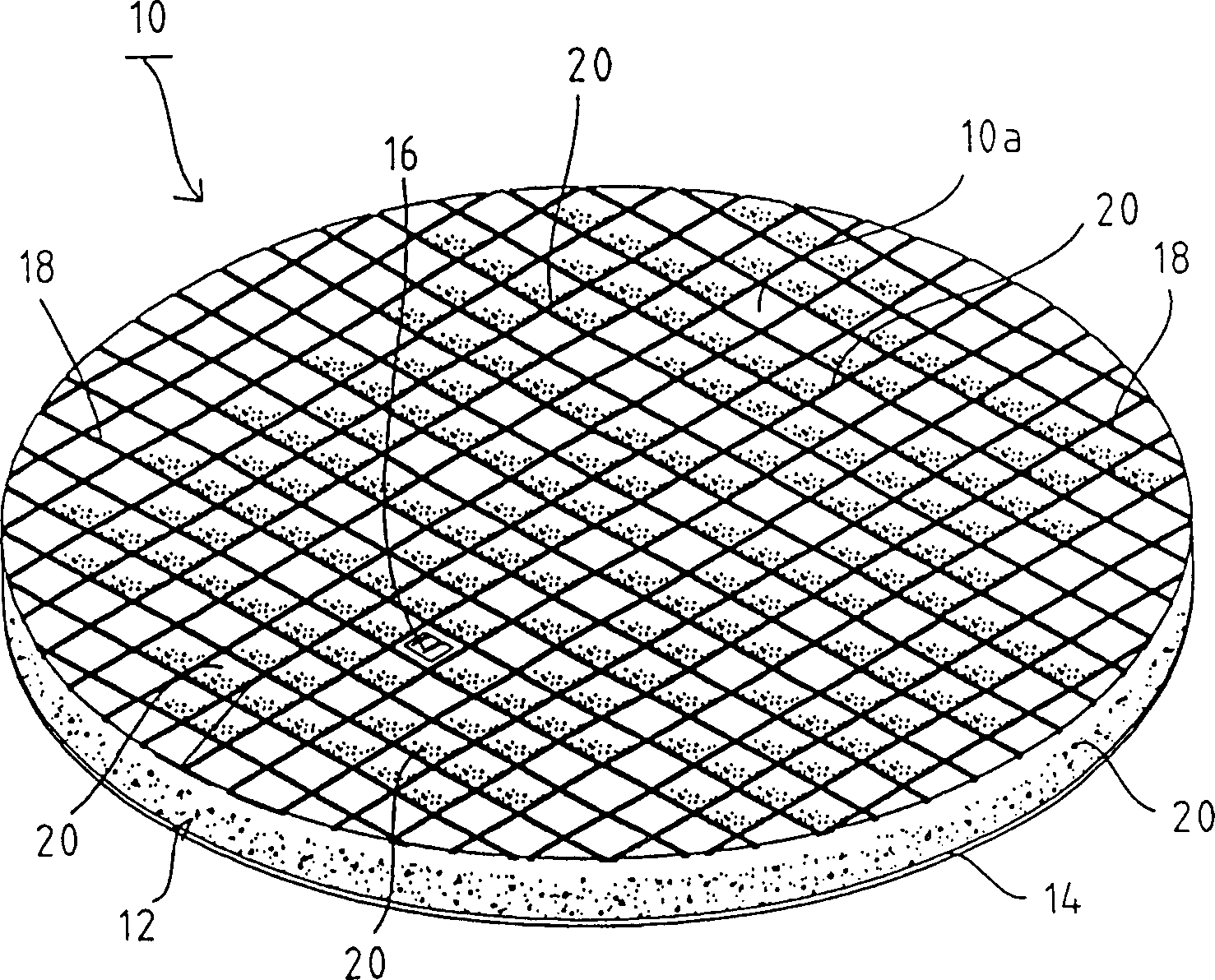
[0022] Such as figure 1 As shown, the polishing pad 10 of this embodiment exists in the form of a circular sheet and basically contains a polyurethane-based foam 12 constituting a polishing surface 10a and a cushioning pad 14 which is integral...


PUM

PropertyMeasurementUnit
densityaaaaaaaaaa
densityaaaaaaaaaa
diameteraaaaaaaaaa

Abstract

A high quality polishing pad suitable for chemical mechanical polishing (CMP) of semiconductor wafer, etc. which is not affected by the change of polishing conditions during polishing and can attain excellent removal rate, capacity of step height reduction and uniformity is described, wherein a polyurethane-based foam 12 having fine and uniform cells 20 suitable for polishing of semiconductor material, etc. obtained by reaction-injection molding a gas-dissolved raw material prepared by dissolving an inert gas in a mixture of a polyurethane or polyurea as a main raw material and various subsidiary raw materials under pressure is used.

Description

technical field [0001] The present invention relates to a polishing pad, and more particularly to a polishing pad suitable for chemical mechanical polishing (CPC), capable of polishing components requiring high precision and surface smoothness, such as semiconductor wafers. Background technique [0002] One of the important technologies supporting recent rapid technological progress is the development of information technology such as computers. It is difficult to say that the above-mentioned development of information technology performance can be obtained by development of performance and integration of CPU (Central Processing Unit) of information engineering equipment such as ULSI (Ultra Large Scale Integration) device constituting the CPU. As one of the methods for rapidly developing the performance and integration of ULSI devices, a method has been practiced, which includes: developing horizontal integration of USLI, that is, finely dividing components, and simultaneous...

Claims


Application Information

Patent Timeline
Patent Type & Authority Applications(China)
IPC IPC(8): B24B37/20B24B37/24B24B37/26B24D3/26B24D13/14B29C45/00B29C45/37B29K75/00B29K105/04B29L31/00C08G18/00C08G101/00C08J5/14H01L21/304
CPCB24D3/26B24B37/26B24B37/24B29B7/7694B29B7/826C08J5/00
Inventor 日紫喜诚吾
Owner ROGERS INOAC CORP
Why Eureka
Try Eureka