Piezoelectric ink jet printing head and its producing method

An inkjet printing head and manufacturing method technology, applied in printing and other directions, can solve the problems of uneven shrinkage of ceramic materials, limiting inkjet printing resolution, and inability to increase the density of inkjet printing heads, etc.

Inactive Publication Date: 2003-04-09
NANODYNAMICS INC
View PDF0 Cites 7 Cited by
  • Summary
  • Abstract
  • Description
  • Claims
  • Application Information

AI Technical Summary

Problems solved by technology

[0008] (2) Since the structure of the piezoelectric inkjet print head is quite complicated, the shrinkage of the ceramic material is often uneven during high-temperature sintering, resulting in stress damage to the internal structure, thereby relatively increasing the failure rate of the finished product;
[0009] (3) Since the structure of the piezoelectric inkjet print head is quite complicated, the shrinkage of the ceramic material will be uneven during sintering at high temperature, which will lead to a piezoelectric inkjet print head with a denser structural design, and the qualified rate of the finished product The lower, thus unable to increase the density between inkjet printheads, and limit the resolution of inkjet printing

Method used


Image

  • Piezoelectric ink jet printing head and its producing method
  • Piezoelectric ink jet printing head and its producing method
  • Piezoelectric ink jet printing head and its producing method

Examples


Embodiment Construction

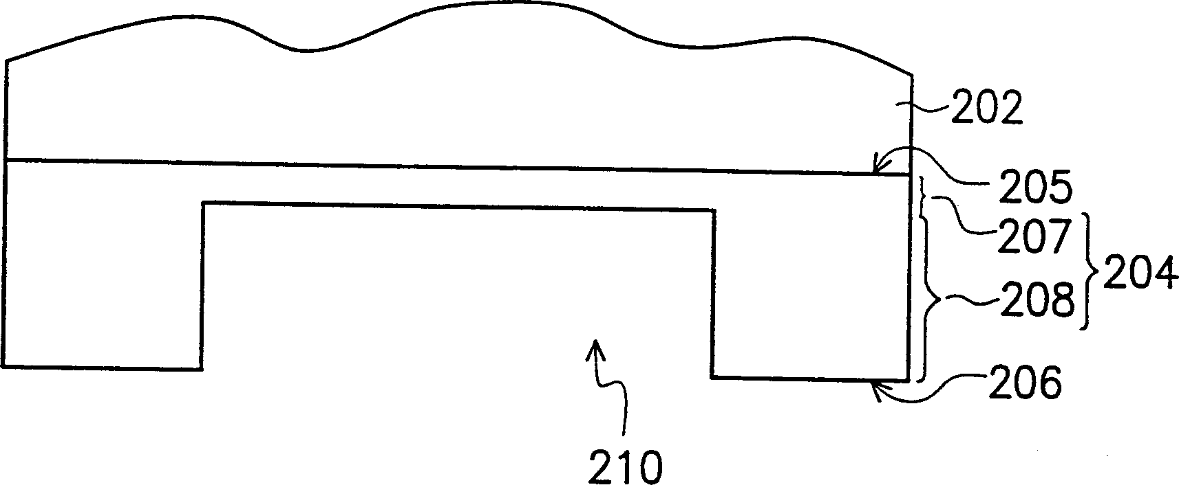
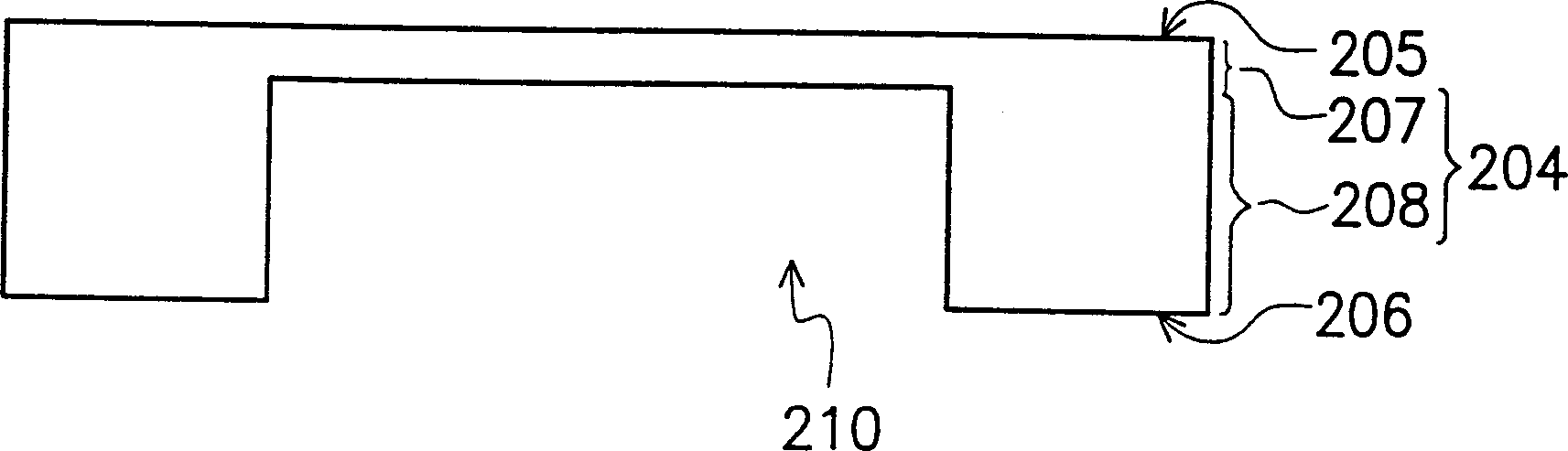
[0037] Please refer to Figure 2A-2D, is a cross-sectional flow chart of a method of manufacturing a piezoelectric inkjet print head according to an embodiment of the present invention. First, if Figure 2A As shown, a substrate 202 is provided, and its material is, for example, silicon, ceramics, metal, etc., and a metal layer 204 (metal layer) is formed on the substrate 202 by means of electroplating, and then lithography ( photolithography) and etching (etching), remove part of the metal layer 204 to form a groove 210, wherein the groove 210 is sunk in the second surface 206 of the metal layer 204, it is worth noting that the groove 210 is half-etched (half etching), so it does not completely penetrate the metal layer 204, so that the depth of the groove 210 is slightly smaller than the thickness of the metal layer 204, and the metal layer 204 is divided into a first metal layer 207 and a first metal layer 207. The second metal layer 208 . Among them, the function of the...


PUM

PropertyMeasurementUnit
melting pointaaaaaaaaaa

Abstract

The piezoelectric ink jet printing head has one notched metal layer to replace normal ceramic vibrating layer and ink cavity layer to avoid the stress destruction caused by high temperature sintering. The producing electroplating and micro-etching process includes forming one notched metal layer on a substrate, removing the substrate, forming the lower electrode layer and one figured piezoelectric layer, forming the upper electrode layer, adhering one jet hole sheet to the second surface of the metal layer to constitute one ink cavity together with the notch.

Description

technical field [0001] The invention relates to a piezoelectric inkjet printing head and its manufacturing method, in particular to a metal layer with grooves instead of the known ceramic thick film to form the vibration layer and ink of the piezoelectric inkjet printing head. The structure of the cavity layer and its manufacturing method. Background technique [0002] The main working principles of traditional inkjet printing technology can be divided into thermal bubble type and piezoelectric type. Thermal bubble jet printing technology uses a heater to vaporize the ink instantly, and generates high-pressure bubbles to push the ink out of the nozzle. Due to the low manufacturing cost of the thermal bubble inkjet print head, it has been successfully commercialized by HP and CANON, and has formed a considerable inkjet printer market. However, due to its working principle of high-temperature gasification, the selectivity of applicable inks (mainly water-based solvents) is l...

Claims


Application Information

Patent Timeline
Patent Type & Authority Applications(China)
IPC IPC(8): B41J2/14B41J2/16
Inventor 林振华吕文崇
Owner NANODYNAMICS INC
Why Eureka
Try Eureka