Breaking method and device for underground well structure layer

A technology of structural layer and equipment, applied in the direction of earthwork drilling, wellbore/well components, production fluid, etc., which can solve problems such as large friction coefficient, reduce hydrostatic effect, and improve drilling pressure

Inactive Publication Date: 2003-04-09
HALLIBURTON ENERGY SERVICES INC
View PDF0 Cites 3 Cited by
  • Summary
  • Abstract
  • Description
  • Claims
  • Application Information

AI Technical Summary

Problems solved by technology

But foam has a much higher coefficient of friction and reduces the hydrostatic effect, both of which seriously increase the pressure used to handle drilling

Method used


Image

  • Breaking method and device for underground well structure layer
  • Breaking method and device for underground well structure layer
  • Breaking method and device for underground well structure layer

Examples


Embodiment Construction

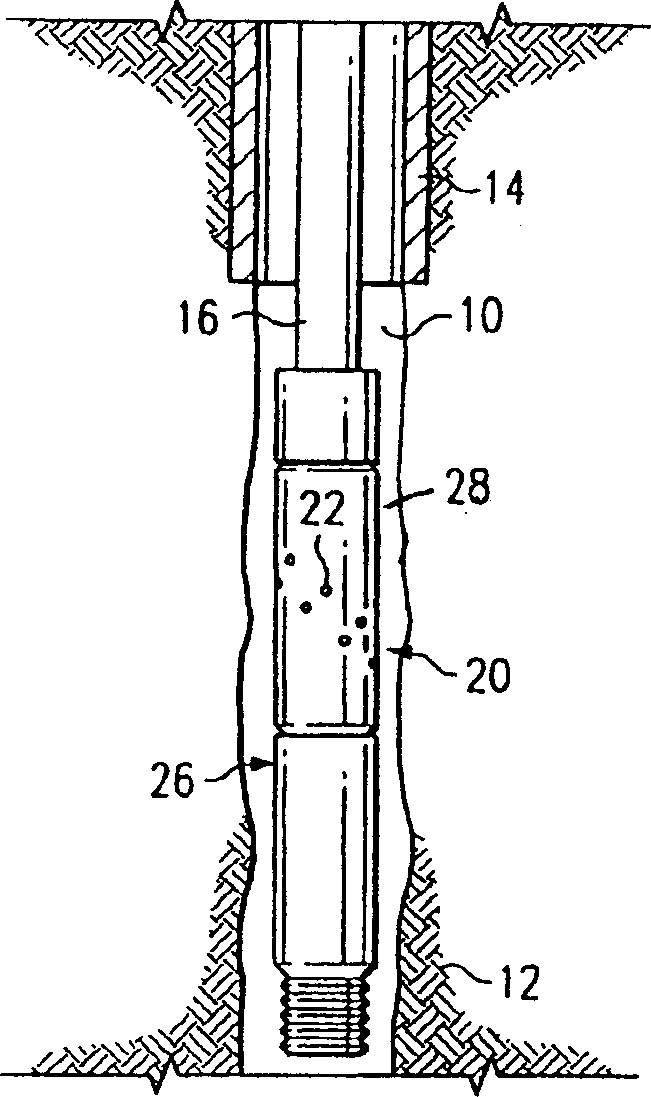
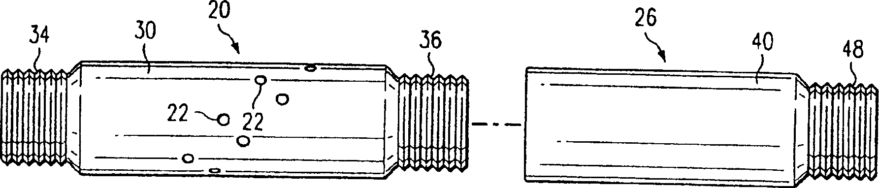
[0017] refer to figure 1 , shows an excitation system according to an embodiment of the present invention installed in a subterranean substantially vertically extending borehole 10 penetrating a subterranean formation 12 producing hydrocarbons. A casing 14 extends from the surface (not shown) into the well 10 and terminates above the formation. The excitation apparatus includes a working string 16 in the form of pipe or coiled tubing extending from the surface through the casing 14 . as from figure 1 As seen in , a working string 16 extends beyond or below one end of the casing 14, and one end of the working string 16 is coupled to one end of a tubular spray sub 20 in a manner to be described. The jet fitting 20 has a plurality of through-holes 22 machined through its wall, forming a discharge jet as will be described in detail below.

[0018] A valve connector 26 is coupled to the other end of the spray connector 20 in a manner that will also be described. As will be desc...


PUM


Abstract

A method of fracturing a downhole formation according to which a plurality of jet nozzles are located in a spaced relation to the wall of the formation to form an annulus between the nozzles and the formation. A non-acid containing stimulation fluid is pumped at a predetermined pressure through the nozzles, into the annulus, and against the wall of the formation, and a gas is introduced into the annulus so that the stimulation fluid mixes with the gas to generate foam before the mixture is jetted towards the formation to form fractures in the formation.

Description

field of invention [0001] The present invention relates to a method and apparatus for treating a subterranean well formation to stimulate the production of hydrocarbons, and more particularly to a method and apparatus for fracturing a well formation. Background technique [0002] Various techniques have been developed for treating subterranean formations to stimulate the production of hydrocarbons. For example, hydraulic fracture acidizing methods are often used, according to which a portion of the formation to be excited is separated by conventional plugging, etc., and an excitation fluid containing gel, acid, mortar, etc. is pumped through the drilled well into the separated portion of the formation middle. The pressurized excitation fluid pushes against the structural layer with a very high force, thereby creating and propagating cracks in the structural layer. But the requirement to separate the structural layers with plugging is time consuming and adds considerably to...

Claims


Application Information

Patent Timeline
IPC IPC(8): E21B43/26E21B43/267
CPCE21B43/267E21B43/26
Inventor 吉姆·B·苏亚阿马查阿利克·陈基思·里斯普勒
Owner HALLIBURTON ENERGY SERVICES INC
Why Eureka
Try Eureka