Calculation method and device for capacity subsidy of compressed air energy storage system

A compressed air energy storage and subsidy technology, which is applied in the storage of electric energy systems, circuit devices, and communication networks with energy trade/energy transmission authority, can solve problems such as difficult incentives, single subsidy methods, and difficult monetization. To achieve the effect of effective motivation

Active Publication Date: 2020-06-23
STATE GRID ANHUI ELECTRIC POWER CO LTD +4
View PDF7 Cites 0 Cited by
  • Summary
  • Abstract
  • Description
  • Claims
  • Application Information

AI Technical Summary

Problems solved by technology

However, the valuable services provided by energy storage, such as frequency regulation, peak shaving, spinning reserve, black start, peak-valley arbitrage, etc., are difficult to monetize, that is, there is no price signal to reflect its actual value
Therefore, in the absence of subsidies, it is difficult for energy storage power stations to cover costs, and manufacturers lack motivation to invest in energy storage capacity construction
[0004] The existing energy storage subsidy method is mainly based on the two-part electricity price, but there are problems with rough calculation methods and a single subsidy method, which cannot reflect the actual value of energy storage power stations, and it is difficult to achieve effective incentives

Method used


Image

  • Calculation method and device for capacity subsidy of compressed air energy storage system
  • Calculation method and device for capacity subsidy of compressed air energy storage system
  • Calculation method and device for capacity subsidy of compressed air energy storage system

Examples


Embodiment Construction

[0023] In order to make the purpose, technical solutions and advantages of the embodiments of the present invention clearer, the technical solutions in the embodiments of the present invention will be clearly and completely described below in conjunction with the drawings in the embodiments of the present invention. Obviously, the described embodiments It is a part of embodiments of the present invention, but not all embodiments. Based on the embodiments of the present invention, all other embodiments obtained by persons of ordinary skill in the art without creative efforts fall within the protection scope of the present invention.

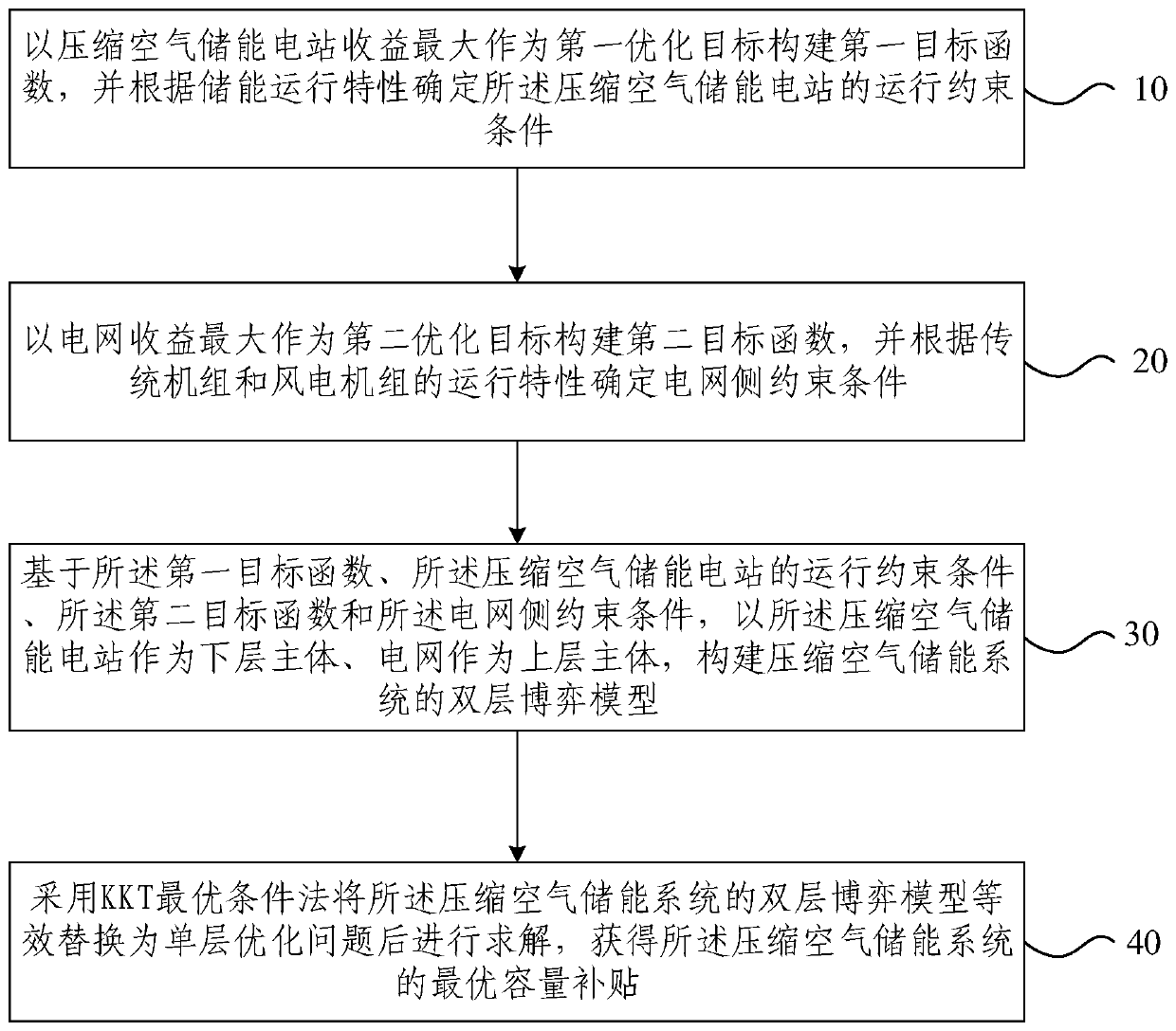
[0024] The working principle of the compressed air energy storage system is to use low-peak electricity, abandoned wind power, and abandoned photovoltaics to compress the air, seal and store the high-pressure air, and release the compressed air to drive the turbine to generate electricity during the peak load period of the grid.

[0025] In order ...


PUM


Abstract

The invention provides a capacity subsidy calculation method and device for a compressed air energy storage system. The method comprises steps that a first target function is constructed through taking the maximum revenue of a compressed air energy storage power station as a first optimization goal, and operation constraints of the compressed air energy storage power station are determined according to energy storage operation characteristics; a second target function is constructed through taking the maximum revenue of a power grid as a second optimization goal, and power grid side constraints are determined according to operation characteristics of a conventional unit and a wind turbine generator; based on the first target function, the operation constraints of the compressed air energystorage power station, the second target function and the power grid side constraints, taking the compressed air energy storage power station as a lower-level main body and the power grid as an upper-level main body, a two-level game model is constructed; the two-level game model is transformed into a single-level model for solution through utilizing the KKT condition method, and the optimal capacity subsidy of a compressed air energy storage system is obtained. The method is advantaged in that the theoretical basis can be provided for power grid enterprises to develop capacity subsidy strategies.

Description

technical field [0001] Embodiments of the present invention relate to the technical field of compressed air energy storage, and more specifically, to a method and device for calculating capacity subsidies of a compressed air energy storage system. Background technique [0002] Renewable energy represented by wind energy and solar energy has the advantages of large reserves, easy acquisition, clean and pollution-free, and is an important means to deal with the increasingly serious energy crisis and environmental pollution problems. However, as the installed capacity of renewable energy increases, its inherent intermittency and uncertainty will seriously affect the safe and stable operation of the power grid. A large-capacity energy storage system has a strong ability to transfer energy in time and space, which can provide flexible services for all links in the power value chain, and provide an effective means for realizing the low-carbon transformation of the power system. ...

Claims


Application Information

Patent Timeline
Patent Type & Authority Patents(China)
IPC IPC(8): H02J3/00H02J3/28H02J15/00
CPCH02J3/008H02J3/28H02J15/006H02J2203/20Y02E10/76Y02P80/10Y02P80/20
Inventor 梅生伟林其友陈来军潘静卢强陈锋郑天文傅中薛小代
Owner STATE GRID ANHUI ELECTRIC POWER CO LTD
Why Eureka
Try Eureka