A Magnetically Coupled Non-Resonant Rotating Piezoelectric Generator

A non-resonant, rotary pressure technology, applied in the direction of generator/motor, piezoelectric effect/electrostrictive or magnetostrictive motor, electrical components, etc., can solve the problem of low frequency modulation ability, difficult precise control, low power generation efficiency, etc. question

Active Publication Date: 2020-07-07
ZHEJIANG NORMAL UNIVERSITY
View PDF2 Cites 0 Cited by
  • Summary
  • Abstract
  • Description
  • Claims
  • Application Information

AI Technical Summary

Problems solved by technology

Although the gyromagnetic excitation solves the problem of impact and noise to a large extent, it still cannot avoid the problem of low power generation efficiency caused by the mismatch between the excitation frequency and the natural frequency of the generator under different working environments
In order to adapt to the working environment under different excitation frequencies, the concept of adjustable frequency is proposed. For example, Chinese patents 201210592977.8 and 201310211521.7 respectively conduct frequency modulation by electronic control and introducing nonlinear force, but the frequency modulation ability of the former is low, while the latter is due to the nonlinearity of magnetic force. Therefore, it is not easy to control accurately; in addition, both of them use the cantilever beam piezoelectric vibrator as the power generation unit, so it is easy to be damaged during the work process, and the safety is poor

Method used


Image

  • A Magnetically Coupled Non-Resonant Rotating Piezoelectric Generator
  • A Magnetically Coupled Non-Resonant Rotating Piezoelectric Generator
  • A Magnetically Coupled Non-Resonant Rotating Piezoelectric Generator

Examples


Embodiment Construction

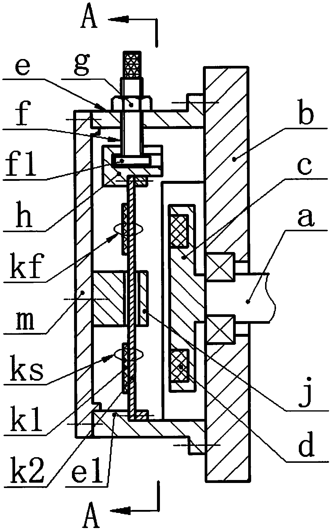
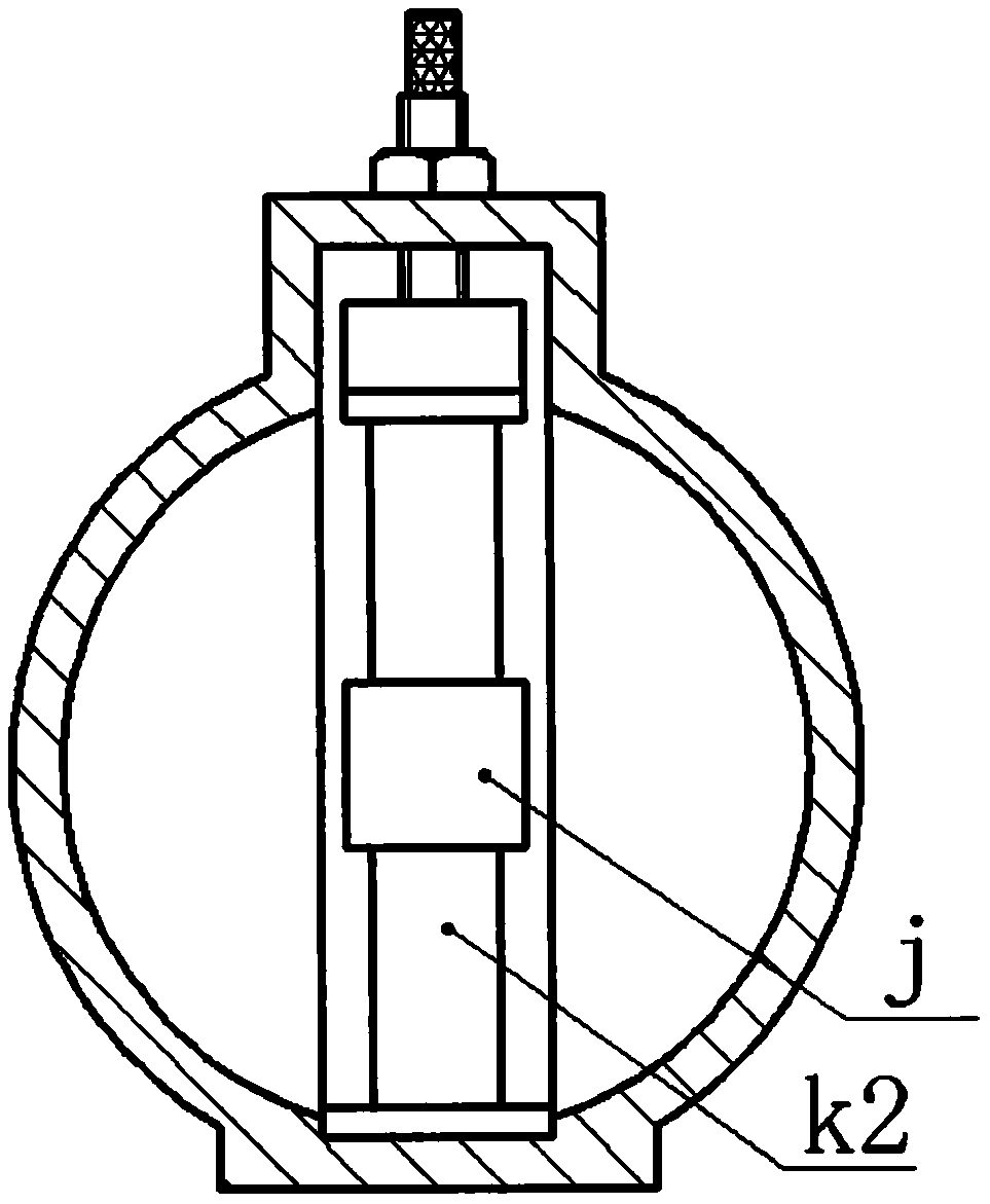
[0016] The rotating shaft a is installed on the bottom shell b via a bearing, and a turntable c is installed at the end, and the end surface of the turntable c is uniformly inlaid with excitation magnets d; the right flange end of the shell e is installed on the bottom shell b via screws, The left side is equipped with an end cover m through screws; the top of the shell e is provided with a threaded hole, and the inside is provided with a boss e1; the adjusting bolt f protrudes from the inside of the shell e through the threaded hole, and a lock nut g is screwed on the outside; The bottom of the adjusting bolt f is provided with a circular boss f1, and the circular boss f1 extends into the gap of the loading block h; the two ends of the ferromagnetic substrate k1 are respectively installed on the loading block h and the boss e1 through screws and pressure blocks, and the middle part Its lateral displacement is constrained by the guide block j with a gap, and thus divided into u...


PUM


Abstract

The invention relates to a magnetically coupled non-resonant rotary piezoelectric generator, and belongs to the technical field of power generating. A rotating shaft is installed on a bottom shell, arotating disc is installed at the end part of the magnetically coupled non-resonant rotary piezoelectric generator, and an exciting magnet is welded on the end surface of the rotating disc; the rightside of the shell body is installed on the bottom shell, and an end cover is installed on the left side of the shell body; a threaded hole is formed in the top end of the shell body, and a raised table is arranged on the inner side of the shell body; an adjusting bolt extends out of the inner part of the shell body through the threaded hole, and a lockage nut is arranged outside the shell body ina spiraling mode; a circular raised table arranged on the bottom of the adjusting bolt extends into an opening of a loading block; the two ends of ferromagnetic substrate are correspondingly installedon the loading block and the raised table, lateral displacement of the ferromagnetic substrate is limited through a guiding block arranged on the middle of the ferromagnetic substrate, and thus the ferromagnetic substrate is divided into an upper piezoelectric oscillator and a lower piezoelectric oscillator; the guiding block is installed on the end cover; the upper piezoelectric oscillator and the lower piezoelectric oscillator are formed by bonding of the ferromagnetic substrate and a piezoelectric crystal plate, and the piezoelectric crystal plate is arranged on the left side of the ferromagnetic substrate; when the adjusting bolt is adjusted to an upper limit position, the upper piezoelectric oscillator and the lower piezoelectric oscillator are in elastic deformation, and when the adjusting bolt is adjusted to a lower limit position, the upper piezoelectric oscillator and the lower piezoelectric oscillator are in the largest allowable compressive stress range.

Description

technical field [0001] The invention belongs to the technical field of power generation, and in particular relates to a magnetically coupled non-resonance rotating piezoelectric generator. Background technique [0002] With the popularization of micro-power wireless sensors and distributed sensing technologies in the fields of health monitoring, aerospace and program control systems, the environmental pollution caused by chemical batteries as the main energy supply method cannot be ignored. For this reason, miniature generators that recycle energy such as vibration energy, human body motion energy, rotational kinetic energy and fluid energy in the natural environment are widely favored at home and abroad. The rotary piezoelectric generator is one of the important methods to recover the kinetic energy of the rotating body. The main ways to realize energy recovery are inertial excitation, toggle excitation, impact excitation and gyromagnetic excitation. Among them, gyromagneti...

Claims


Application Information

Patent Timeline
Patent Type & Authority Patents(China)
IPC IPC(8): H02N2/18
Inventor 张忠华吕鹏万嫩阚君武王淑云张昱程光明林仕杰
Owner ZHEJIANG NORMAL UNIVERSITY
Why Eureka
Try Eureka