Press button type switch and its producing method

A switch and button technology, applied in the field of button switches and its manufacturing, can solve problems such as poor contact and achieve the effect of preventing cutting

Inactive Publication Date: 2003-04-09
HOKURIKU ELECTRIC INDS
View PDF0 Cites 1 Cited by
  • Summary
  • Abstract
  • Description
  • Claims
  • Application Information

AI Technical Summary

Problems solved by technology

[0003] However, even with such a push-button switch, poor contact may occur between the ridge line of the center contact and the periphery of the movable contact hole.

Method used


Image

  • Press button type switch and its producing method
  • Press button type switch and its producing method
  • Press button type switch and its producing method

Examples


Embodiment Construction

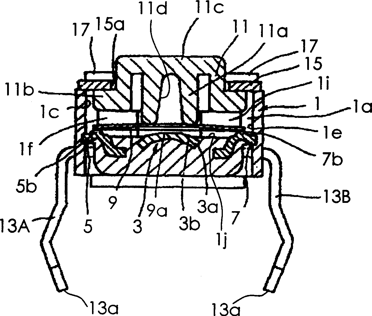
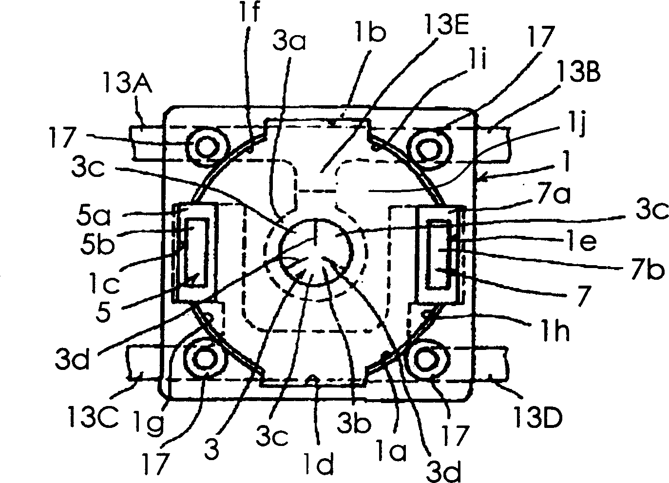
[0020] Hereinafter, embodiments of the present invention will be described in detail with reference to the drawings. figure 1 It is a schematic cross-sectional view of a push-button switch according to an embodiment of the present invention, figure 2 Yes figure 1 The shown top view of the insulating case main body of the push-button switch viewed from the side of the opening of the recess. As shown in each figure, the push button switch of this embodiment has an insulating case main body 1, a central contact 3, a pair of end contacts 5, 7, a movable contact 9, and an operating member 11. The insulating case main body 1 has a quadrangular prism shape, and a cylindrical recess 1a opening upward is formed inside. The inner surface of the concave portion 1a has flat surfaces 1b to 1e having flat surfaces projecting in four directions and curved surfaces 1f to 1i connected to the flat surfaces 1b to 1e at intervals of 90°. These curved surface portions 1f to 1i respectively for...


PUM


Abstract

The invention provides a push-on switch capable of preventing inferior conduction between a ridge of a central part contact and the circumferential edge of a hole part of a movable contact. An acute angle between a virtual perpendicular L passing through a convergent point C of the ridge 3d of the central part contact 3 and perpendicularly extending to the bottom of a recess part of an insulating case body 1 and the ridge 3d is set to 83 degree-89 degree.

Description

technical field [0001] The invention relates to a key switch and a manufacturing method thereof. Background technique [0002] As a push-button switch, there are: an insulating case main body having a concave portion; a flat central part contact and an end part contact fixed in the insulating case main body; A movable contact whose central part protrudes toward the opening provided in the recess and is bent so as to be reversible; and an operating member that brings the peripheral part of the movable contact hole into contact with the central part. However, in such a push-button switch, there is a problem in that dirt, dust, etc. adhere to the flat central contact, resulting in poor contact between the central contact and the movable contact. Therefore, it has been proposed to form a polyhedral center contact that protrudes toward the hole of the movable contact and has at least two ridgelines converging toward the tip on its outer surface. In this configuration, the acute...

Claims


Application Information

Patent Timeline
Patent Type & Authority Applications(China)
IPC IPC(8): H01H13/10H01H1/06H01H11/00H01H13/12H01H13/14H01H13/48H01H13/52
Inventor 上野聪多田守男
Owner HOKURIKU ELECTRIC INDS
Why Eureka
Try Eureka