
Connecting switchover control type capacitor accumulator

A technology for connecting switching and power storage devices, applied to battery circuit devices, circuit devices, DC network circuit devices, etc., to reduce power loss and improve efficiency reduction

Inactive Publication Date: 2003-04-09
アドバンストキャパシタテクノロジーズ +1
View PDF6 Cites 4 Cited by
  • Summary
  • Abstract
  • Description
  • Claims
  • Application Information

AI Technical Summary

Problems solved by technology

Also, in any stage, there is only one switch connected in series with the capacitor, so when a semiconductor is used as the switch, the loss caused by the turn-on voltage of the switch in question can be minimized

Method used

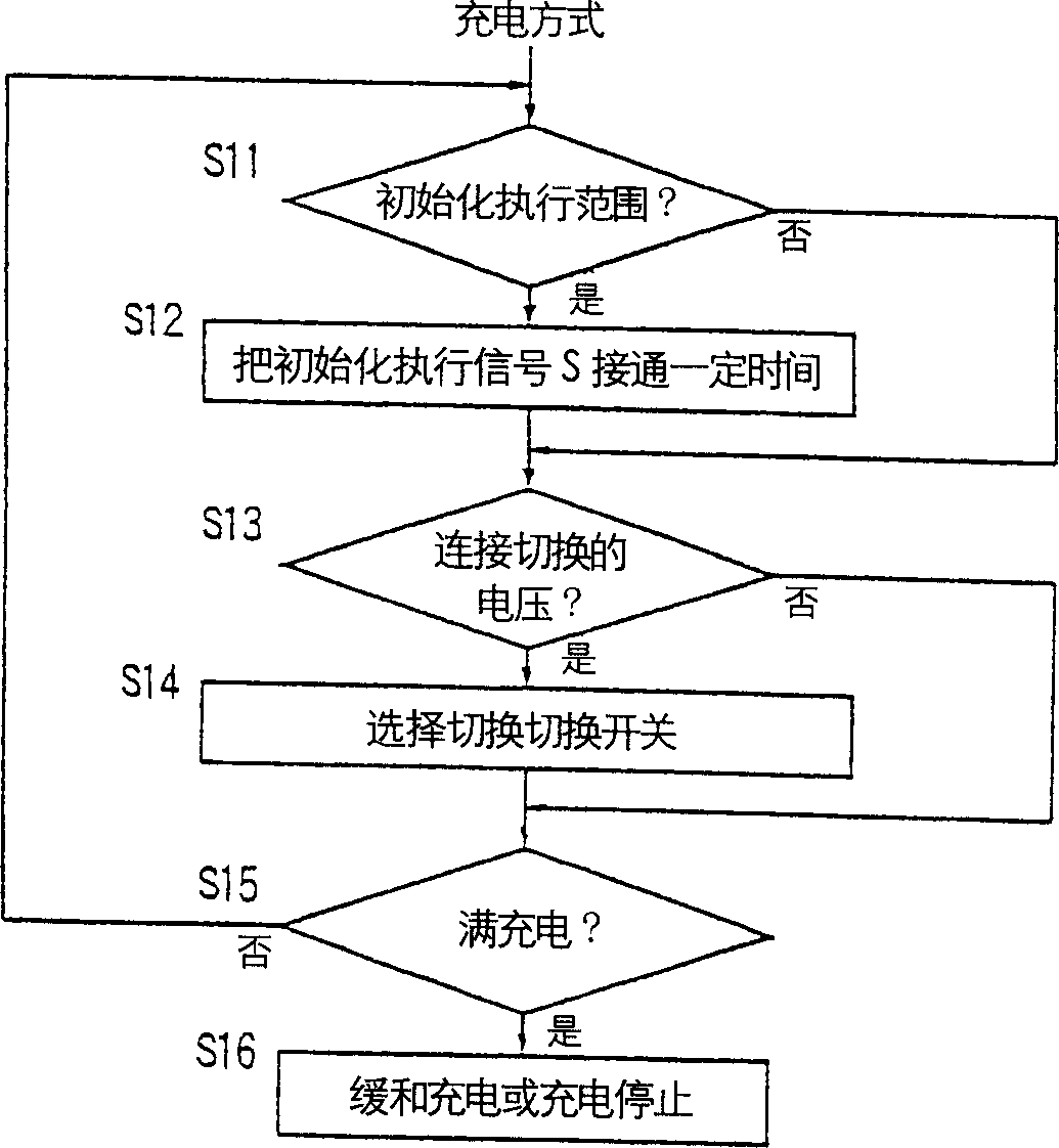

Image

  • Connecting switchover control type capacitor accumulator
  • Connecting switchover control type capacitor accumulator
  • Connecting switchover control type capacitor accumulator

Examples


Embodiment Construction

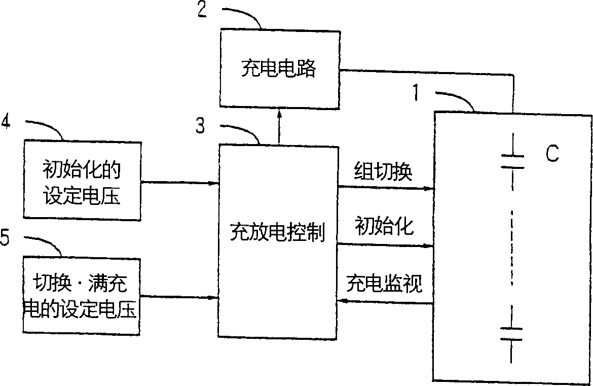
[0033] Embodiments of the present invention will be described below with reference to the drawings. figure 1 It is a figure which shows the Example of the connection switching control type capacitor power storage device concerning this invention. 1 is a power storage unit, 2 is a charging circuit, 3 is a charge-discharge control unit, 4 is a setting voltage for initialization, 5 is a setting voltage for switching and full charging, and C denotes a capacitor.

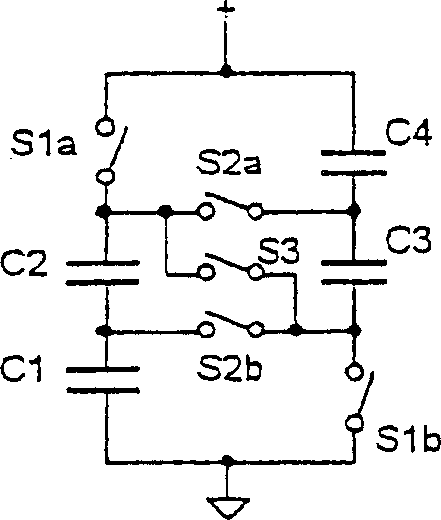
[0034] exist figure 1 Among them, the power storage unit 1 includes Figure 5 6 (A) ~ (G) with a plurality of capacitors C with parallel monitors, switches for switching them in series and parallel, the parallel monitor with initialization function and the connection switching function of capacitor C are provided. The charging circuit 2 is a circuit that controls the charging current to charge the capacitor C of the power storage unit 1 in a charging method such as constant current charging and gentle charging. The c...


PUM


Abstract

A connection-switched capacitor storage system comprises plural capacitors, parallel monitors connected with the capacitors, respectively, switches for switching the connections of the capacitors from a series combination to a parallel combination or vice versa, and a control portion. The parallel monitors bypass the charging current for the capacitors when the terminal voltages of the capacitors exceed a given voltage, thus limiting increases of the terminal voltages of initializing the terminal voltages of the capacitors to their original level. The control portion controls initialization and switching of the connections of the capacitors. The control portion causes the parallel monitors to initialize the capacitors near the voltage at which the connections of the capacitors are switched by the switches.

Description

technical field [0001] The present invention relates to a kind of connection switching control type capacitor power storage device, comprising: a plurality of capacitors; Parallel monitor, connected in parallel with each of the above-mentioned plurality of capacitors, has the function of limiting each capacitor to a value by bypassing the charging current when it is above a predetermined voltage. The initialization function on the set voltage of initialization; the switching device switches the connection of the above-mentioned multiple capacitors from series to parallel or from parallel to series; the control device controls the voltage of the above-mentioned multiple capacitors according to the voltage of the above-mentioned The initialization performed, simultaneously, controls the switching of the capacitor connection performed by the aforementioned switching means. Background technique [0002] A power storage device that combines a capacitor with an electronic circuit,...

Claims


Application Information

Patent Timeline
Patent Type & Authority Applications(China)
IPC IPC(8): H02J1/00H02J7/00
CPCH02J7/0016H02J7/0024
Inventor 冈村迪夫山岸政章
Owner アドバンストキャパシタテクノロジーズ
Learn More