Air suspension system for vehicle

An air suspension and vehicle technology, applied in the field of vehicle air suspension systems, can solve problems such as trouble, inconvenience to workers, and increased manufacturing costs

Inactive Publication Date: 2003-04-16
HYUNDAI MOTOR CO LTD
View PDF0 Cites 13 Cited by
  • Summary
  • Abstract
  • Description
  • Claims
  • Application Information

AI Technical Summary

Problems solved by technology

[0013] However, there is a problem in the air suspension system described in this way according to the prior art, because a large installation space is required to separately install the height control valve 10 and the air spring 30 on the chassis frame 1, thus when the vehicle is manufactured, there will be ...

Method used


Image

  • Air suspension system for vehicle
  • Air suspension system for vehicle
  • Air suspension system for vehicle

Examples


Embodiment Construction

[0022] Embodiments of the present invention will be described in detail below with reference to the accompanying drawings.

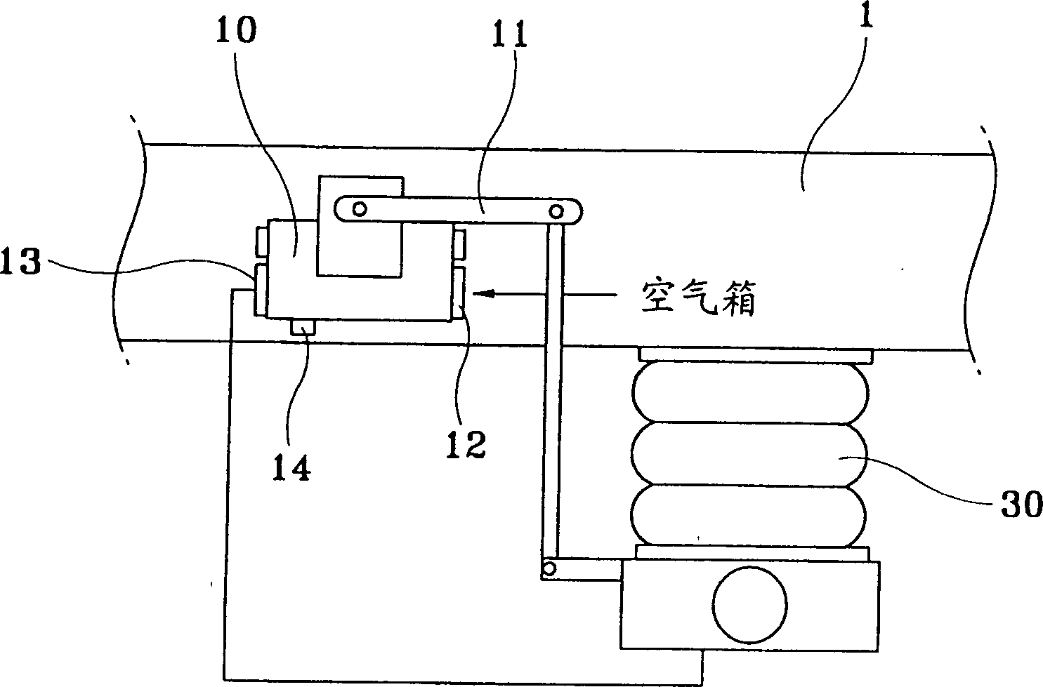
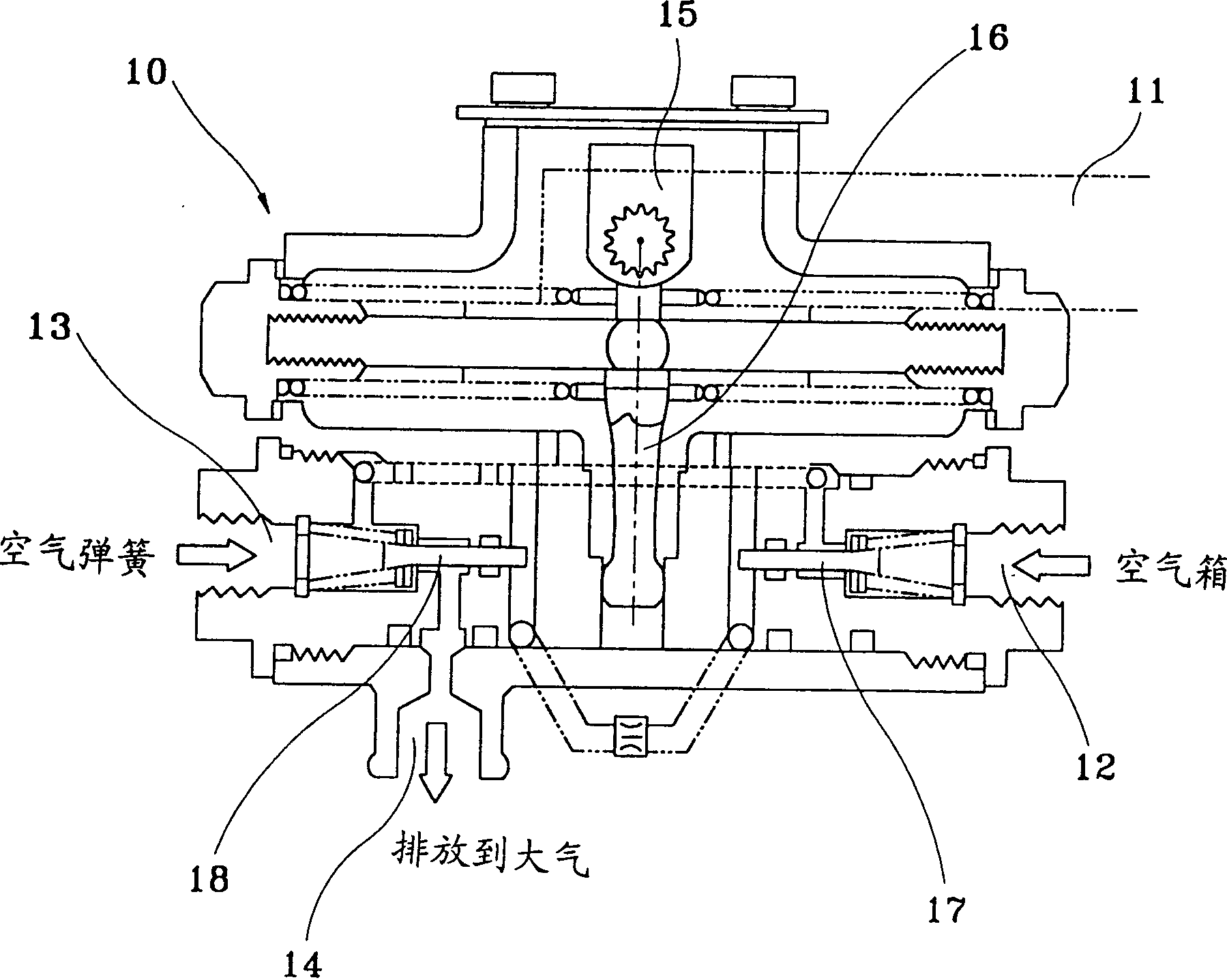
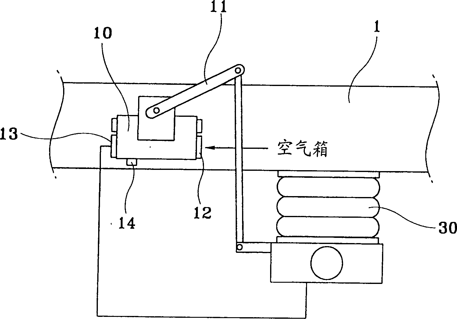
[0023] Such as Figure 4 , Figure 5 and Figure 6 As shown, the valve device for controlling the internal pressure of the air spring 60 is integrally formed in the space occupied by the air spring 60 .

[0024] The air suspension system according to the present invention includes: an air spring 60, whose upper end is connected to the lower part of the chassis frame 1 to directly support the vehicle body; an upper part, which passes through the top of the air spring 60 and is connected to the chassis frame 1 , and a part, which passes through the bottom of the air spring 60 and is connected to the lower end of the air spring 60 and the axle A, wherein the linear sliding of the upper and lower parts causes the change of the total length of the upper and lower parts; and a valve device, which In response to the linear sliding of the upper and lower membe...


PUM


Abstract

An air suspension system for a vehicle wherein a valve means for varying the resilience of an air spring in response to changes of vehicle height is integrally formed with an air spring to be mounted on the vehicle frame such that the installation space of the air suspension system can be minimized. As a result, cumbersome processes involved with the manufacture of the vehicle can be eliminated to provide an improved convenience for workers. A conventional lever used for connecting a leveling valve and an air spring is dispensed with to reduce the number of parts constituting the air suspension system and lower the manufacturing cost.

Description

technical field [0001] The present invention relates to a vehicle air suspension system, and more particularly to a vehicle air suspension system suitable for integrating a height control valve and an air spring to reduce the size of an installation space and reduce manufacturing costs. Background technique [0002] Generally, an air suspension system installed on a commercial vehicle such as a large bus, a heavy truck, etc. includes an air box, a height control valve, an air spring, and the like. The system utilizes aeroelasticity to absorb small vibrations, thereby improving ride comfort and can adjust the height of the vehicle to a predetermined height by means of pressure control. [0003] A height control valve 10 for a vehicle air suspension system is fixedly mounted on a chassis frame 1 shown in FIG. The height control valve 10 and the air spring 30 are connected to each other by a pivot rod 11 . [0004] In addition, the height control valve 10 includes a first val...

Claims


Application Information

Patent Timeline
IPC IPC(8): B60G17/056B60G11/27B60G17/048F16F9/04F16F9/32
CPCB60G2500/2042B60G2400/252F16F9/0481B60G17/0485B60G2202/152B60G2500/2044F16F9/3221B60G2206/42B60G2500/30B60G11/27
Inventor 姜锡和
Owner HYUNDAI MOTOR CO LTD
Why Eureka
Try Eureka