Permanet magnet type rotary electric machine

A technology of rotating electrical machines and permanent magnets, applied to synchronous motors with stationary armatures and rotating magnets, magnetic circuit rotating parts, magnetic circuits, etc., can solve the problems of hindering the insertion of armature windings and small cross-sectional area, etc. Achieve the effect of reducing harmonic components, reducing torque pulse and low noise

Inactive Publication Date: 2003-04-16
HITACHI LTD
View PDF1 Cites 13 Cited by
  • Summary
  • Abstract
  • Description
  • Claims
  • Application Information

AI Technical Summary

Problems solved by technology

However, the farther the ends of the crests are located from the rotor, the smaller the cross-sectional area of ​​the slot becomes, thereby hindering the insertion of the armature winding.

Method used


Image

  • Permanet magnet type rotary electric machine
  • Permanet magnet type rotary electric machine
  • Permanet magnet type rotary electric machine

Examples


Embodiment 1

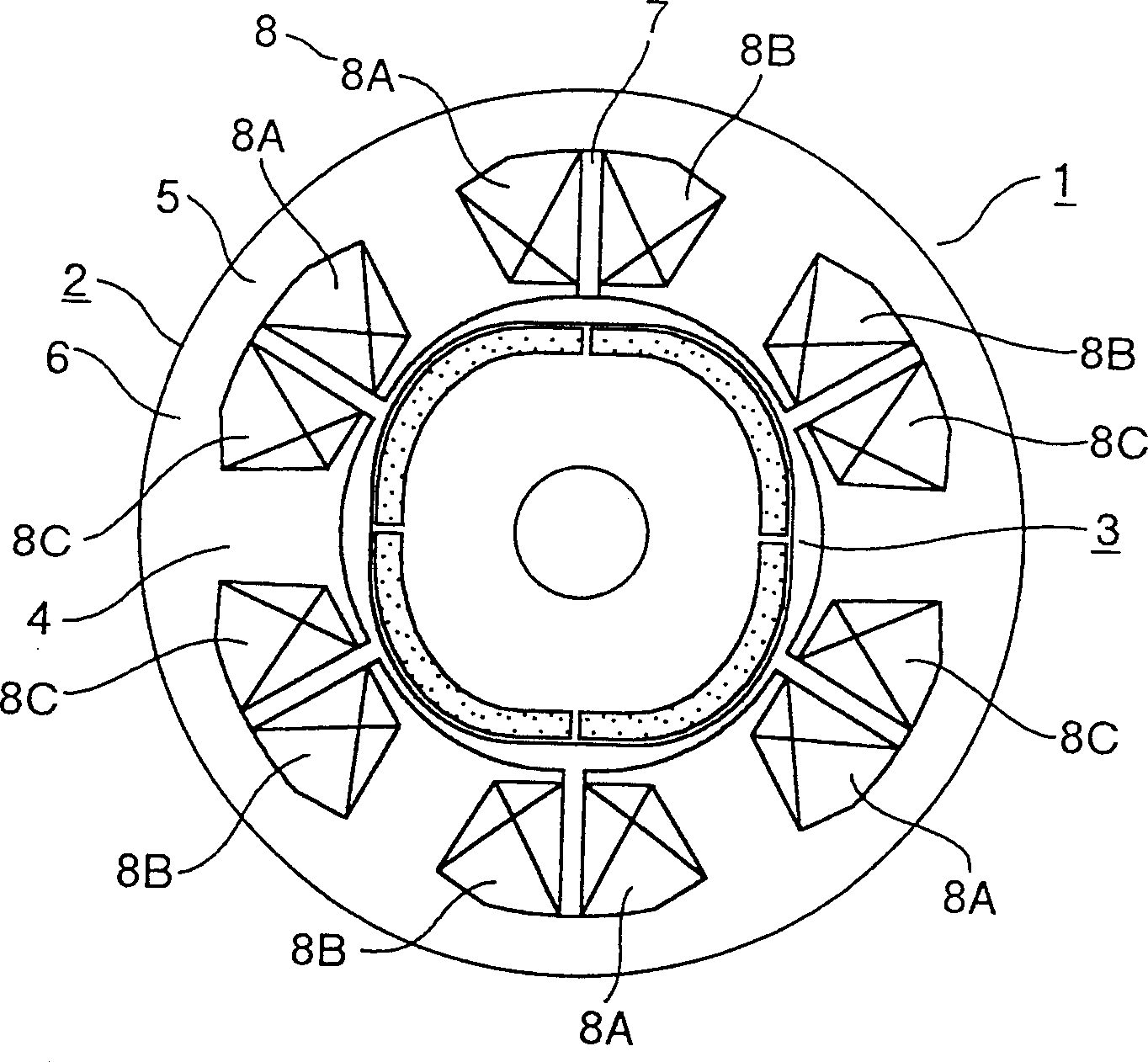
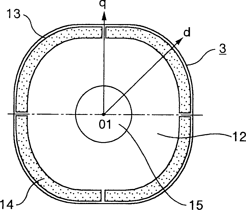
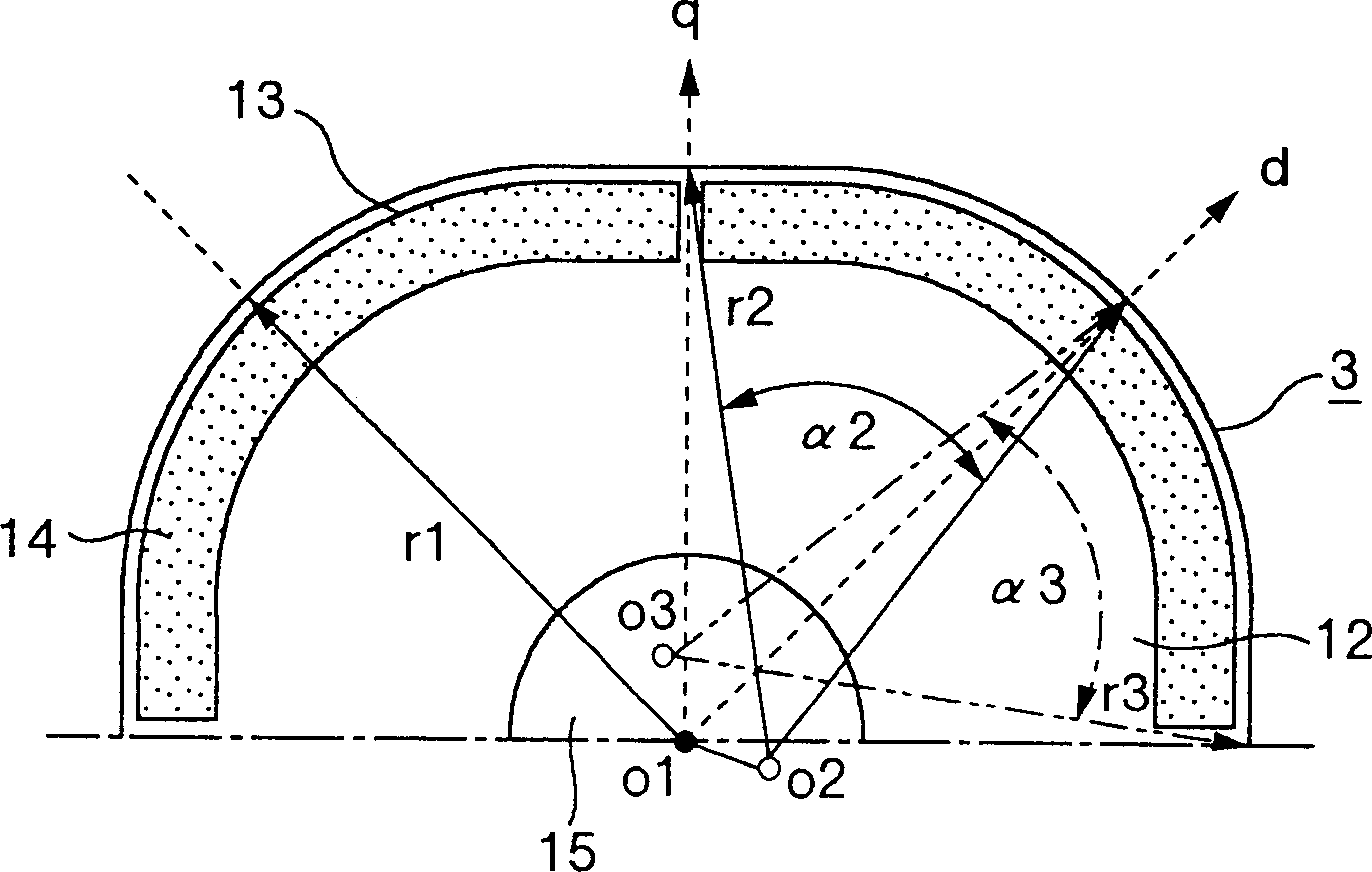
[0023] figure 1 Showing the radial cross-sectional shape of Embodiment 1 of the permanent magnet type rotating electrical machine according to the present invention, figure 2 represents the radial cross-sectional shape of the rotor according to Embodiment 1 of the present invention, image 3 is a cross-sectional view of the outer peripheral shape of the rotor according to Embodiment 1 of the present invention; Figure 4 A waveform representing the induced electromotive force of the permanent magnet type rotating electric machine according to the present invention; Figure 10 It is a cross-sectional view showing the structure of a comparative example of a permanent magnet type rotating electrical machine.

[0024] A permanent magnet type rotating electrical machine 1 includes a stator 2 and a rotor 3 . The stator 2 includes a stator core 6 including teeth 4 and a core back 5, and concentric armature windings 8 (three-phase windings including a U-phase winding 8A, a V-phase ...

Embodiment 2

[0032] Figure 5 It is a cross-sectional view of the outer peripheral shape of the rotor in Embodiment 2 of the permanent magnet type rotating electric machine according to the present invention.

[0033] For the rotor in the attached figure, with image 3 Similar reference numerals are used for similar parts in , and therefore descriptions thereof are omitted. Figure 5 and image 3 The difference is that the outer peripheral shape of the rotor core 12 is a combination of an arc concentric with the center O1 of the rotor 3 and an arc not concentric therewith. Specifically, the shape of the rotor is a combination of arcs around points O2, O3 different from the center O1 and an arc around the center O1. In order to make the outer peripheral shape of the rotor symmetrical with respect to the d axis at each magnetic pole, the radius r2 of the arc around the point O2 is equal to the radius r3 of the arc around the point O3, and the circumferential angle α2 of the arc around the...

Embodiment 3

[0037] Image 6 It is a cross-sectional view of the outer peripheral shape of the rotor of Embodiment 3 of the permanent magnet type rotating electric machine according to the present invention.

[0038] For the rotor in the attached figure, with image 3 Similar components are shown with similar reference numerals, and descriptions thereof are omitted. Image 6 and image 3 The difference is that the outer peripheral shape of the rotor core 12 is a combination of elliptical arcs whose major axis is along the d-axis direction. In this structure, the radial distance from the center of the rotor 3 to the outer circumference of the rotor 3 still gradually decreases from the d-axis to the q-axis, and thus the same as image 3 Similar advantages are shown for the embodiment shown.


PUM


Abstract

A permanent magnetic type electric rotating machine includes: a stator having armature winding arranged in several slots formed in a stator core; and a rotor having permanent magnets held in several permanent magnetic insertion holes formed in a rotor core, in which a peripheral surface of the rotor core is configured to be a combination of arcs around two points different from a center of the rotor core for each magnetic pole in such a manner that when an axis extending in a central direction of a magnetic pole of the rotor is a d axis, and an axis extending in a direction between magnetic poles that is offset from the central direction of the magnetic pole by 90 electrical degrees is a q axis, a radial distance from a center of the rotor core to a periphery of the rotor is reduced gradually from the d axis to the q axis.

Description

technical field [0001] The present invention relates to a permanent magnet type rotating electric machine having a permanent magnet for forming a field in a rotor, and more particularly, to a permanent magnet type rotating electric machine suitable for use in a compressor of an air conditioner, a refrigerator or a freezer . Background technique [0002] In this type of permanent magnet type rotating electric machine, various attempts have been made regarding reducing noise and vibration, that is, reducing torque pulses. For example, as described in the specification of JP-U-3-106869, the center of the addendum of the stator forms a circle concentric with the rotor core, and both ends of the addendum are formed in a straight line, that is, parallel to the rotor. disengaged to reduce torque. [0003] When a harmonic current passes through the armature winding of a permanent magnet type rotating electrical machine, a harmonic flux is generated, resulting in an increase in tor...

Claims


Application Information

Patent Timeline
Patent Type & Authority Applications(China)
IPC IPC(8): H02K1/22F04B35/04F25B49/02H02K1/00H02K1/18H02K1/24H02K1/27H02K21/12H02K21/14H02K21/16H02K21/22H02K29/06
CPCF25B49/025Y02B30/741H02K1/2786H02K29/06H02K1/187F25B2600/021F04B35/04H02K21/22H02K1/2766H02K1/2733H02K7/14H02K21/14Y02B30/70H02K1/2791
Inventor 高畑良一湧井真一小原木春雄菊地聪高桥身佳
Owner HITACHI LTD
Why Eureka
Try Eureka