Drum taper tool and method for side milling complex cambered centrifugal impeller using drum taper tool

A tool and curved surface technology, which is applied in the field of drum-cone cutters and side milling of complex curved surfaces using drum-cone cutters, which can solve the problems of not being able to find the machining position of the tool, demanding the direction of the tool, and not being able to twist the blade too much

Inactive Publication Date: 2003-04-30
XI AN JIAOTONG UNIV
View PDF0 Cites 40 Cited by
  • Summary
  • Abstract
  • Description
  • Claims
  • Application Information

AI Technical Summary

Problems solved by technology

[0004] In practice, it has been found that the use of conical cutters to process arbitrary curved surfaces has the following defects: 1) This method has strict requirements on the shape of the blade to be processed and the direction of the cutter during processing, and the

Method used


Image

  • Drum taper tool and method for side milling complex cambered centrifugal impeller using drum taper tool
  • Drum taper tool and method for side milling complex cambered centrifugal impeller using drum taper tool
  • Drum taper tool and method for side milling complex cambered centrifugal impeller using drum taper tool

Examples


Embodiment

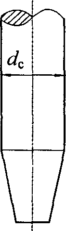
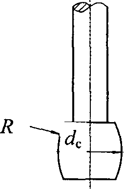
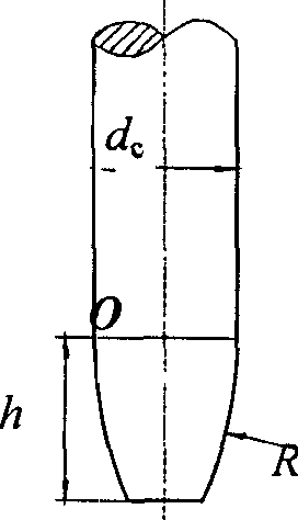
[0073] Using the spherical cutter and the drum-conical cutter respectively, the tool path generation in five-coordinate machining of centrifugal impeller blades is discussed. The blade is an arbitrary curved surface, represented by bicubic B-spline. The diameter of the spherical knife used is d c =32mm, diameter of drum cone cutter rod d c =32mm, R=70mm, h=25mm see figure 1 . The allowable residual height is 0.1mm, and the tool trajectory in blade machining is calculated for the above two tools respectively.

[0074] Calculated as Figure 8 and Figure 9 As shown, the number of trajectories for processing the blade is 16 with a drum-cone cutter, and the total length of the trajectories is 6631mm; while the number of trajectories for a spherical cutter is as many as 39, and the total length of the trajectories is 16453mm, the ratio of the two is 1: 2.5. At the same cutting speed, the processing efficiency of the drum-cone cutter is 2.5 times that of the spherical cutter....


PUM


Abstract

A conic drum-shaped cutting tool and its feed pitch, feed step length and method for calculating the position of cutting tool are disclosed. Its cutting part is a rotary surface. Its generating line is an arc with radius R. Its advantages are high productivity, high rigidity and high rotation flexibility. A method for laternally milling a centrifugal blade wheel with complex curved surface with the said cutting tool is also disclosed, which features less number of tracings, short tracing and high productivity.

Description

1. Technical field [0001] The invention relates to the numerical control machining technology of complex curved surfaces such as arbitrary curved surface impellers in the technical field of mechanical processing and numerical control machining, in particular to a drum-cone cutter and a method for side-milling complex curved surfaces using the drum-cone cutter. 2. Background technology [0002] At present, the cutters usually used in the finishing of centrifugal impellers are spherical cutters, which have a small effective cutting radius and low processing efficiency. [0003] C.Y.Wu.(Arbitrary surface flank milling of fan, compressor, and impeller blades.Transactions of the ASME, Journal of Engineering for Gas Turbines and Power, Vol.117, 1995, p534~p539), proposed the use of conical cutter side milling arbitrary curved surface The method of impeller blades, the cutting edge of which is conical, see figure 1 . He broke through the way of thinking that spherical cutters or ...

Claims


Application Information

Patent Timeline
IPC IPC(8): B23C3/00B23C3/18B23C5/10
CPCB23C3/18B23C5/10B23C2210/084
Inventor 席光蔡永林王尚锦
Owner XI AN JIAOTONG UNIV
Why Eureka
Try Eureka