

A parts discharging device
A technology of parts and templates, applied in the field of feeding and discharging in industrial production, can solve the problems of low discharging efficiency and inaccurate discharging, and achieve the effects of fast discharging speed, improved efficiency and high work efficiency.
- Summary
- Abstract
- Description
- Claims
- Application Information
AI Technical Summary
Problems solved by technology
Method used
Image

Examples
Embodiment 1
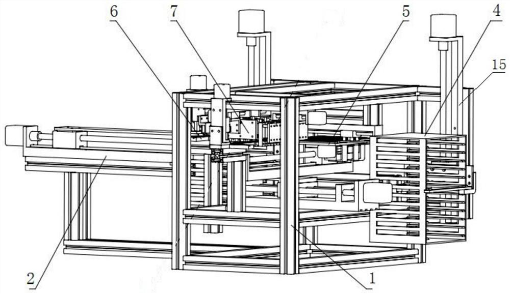
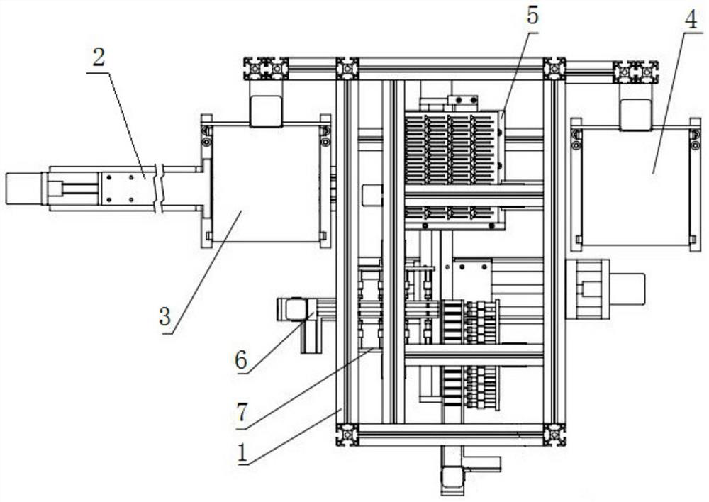
[0034] Such as Figure 1-2As shown, a parts discharge device includes a support frame 1 and a template pushing mechanism 2 arranged on the support frame 1, a first template support 3 for placing a metal template 30 of a bar material 31 to be arranged, and a Place the second template support 4, the moving mechanism 5, the discharge mechanism 6 and the tightening mechanism 7 of the discharged metal template 30; the template pushing mechanism 2 is arranged on the side of the moving mechanism 5, and the first template holder 3 is arranged on the template Between the push-in mechanism 2 and the moving mechanism 5, the second template support 4 is arranged on the other side of the moving mechanism 5 and is opposite to the first template support 3, the discharge mechanism 6 is arranged above the moving mechanism 5, and the jacking mechanism 7 Set above the discharge mechanism 6.
[0035] The parts discharge device of the present invention only needs to place the empty metal template...
Embodiment 2
[0046] The first embodiment is similar to the second embodiment, the difference is that the second embodiment can be used to process the metal template 30 with a T-shaped groove.
[0047] The parts discharge device in this embodiment includes two discharge mechanisms 6, and the two discharge mechanisms 6 are arranged vertically.
PUM
 Abstract
Description
Claims
Application Information